Relay protection exit matrix detection equipment

A detection equipment, relay protection technology, applied in the direction of circuit breaker testing, measuring electricity, measuring devices, etc., can solve the problems of large volume and complexity, hidden safety hazards, low efficiency, etc., to reduce the interference between multiple signals, The effect of meeting the detection requirements and avoiding multi-channel interference

Pending Publication Date: 2021-07-23
国网江苏省电力有限公司淮安供电分公司
View PDF0 Cites 1 Cited by
  • Summary
  • Abstract
  • Description
  • Claims
  • Application Information

AI Technical Summary

Problems solved by technology

[0002] At present, for the detection of the relay protection outlet matrix, it mainly relies on the relay protection tester switch input contact, but only the tripping backup contact can be measured, and the outlet matrix cannot be comprehensively measured, especially in the complex 220kV conventional substation. In the case of outlet matrix, such as 220kV line protection, main transformer protection, bus differential protection and other calibration work, the problem is more prominent; another common method is to use a universal meter to measure the outlet pressure plate one by one, but it needs to repeat the simulation many times The protection action situation is not only large and complicated, low in efficiency, and has potential safety hazards and errors and omissions, but also can only see the data flashing by, and cannot know the amplitude and width of the pulse voltage. The detection data is not accurate and comprehensive, and there is no Accurate data record keeping
Therefore, it will also affect the effect of the detection of the relay protection outlet matrix, leaving hidden dangers for the relay protection to fail to operate correctly. Once the power grid fails, it will directly endanger the stable operation of the power grid

Method used


Image

  • Relay protection exit matrix detection equipment
  • Relay protection exit matrix detection equipment
  • Relay protection exit matrix detection equipment

Examples


Embodiment 1

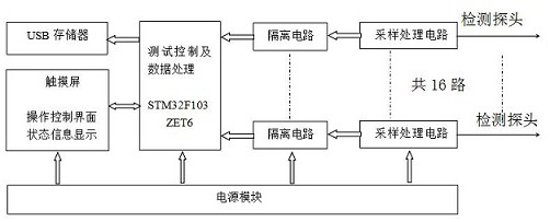
[0026] Such as figure 1 As shown, a relay protection outlet matrix detection equipment includes a power supply module for supplying power to the system, and the power supply module is connected to each module circuit to supply power to it; the system also includes a power supply installed on the detected device 16 detection probes, and sampling processing circuits connected to each detection probe, each sampling processing circuit is connected to the test control and data processing part after passing through the isolation circuit; the output terminals of the test control and data processing part are respectively connected with state information Display interface and storage communication module. The sampling processing circuit has a 16-channel synchronous detection function, which can simultaneously detect the information of the 16-way outlet pressure plate, and transmit it to the data processing center through the isolation circuit; the test control data processing part proc...


PUM


Abstract

The invention discloses relay protection exit matrix detection equipment which comprises a plurality of detection probes arranged on a detected device and sampling processing circuits respectively connected with the detection probes, and each sampling processing circuit is respectively connected with a test control and data processing part through an isolation circuit; the output end of the test control and data processing part is respectively connected with a state information display interface and a storage communication module; each sampling processing circuit has a multi-channel synchronous detection function, can detect information of multi-channel outlet pressing plates at the same time, and transmits the information to the data processing center through the isolation circuit so that mutual interference is reduced; and the test control data processing part processes the received data and transmits the processed data to the state information display part, the test state information of each pressing plate is displayed and maintained in real time, and the amplitude and width of a pulse signal are judged and displayed by a voltage value and an indicating lamp. And the data information can be automatically stored in the mobile memory after the test is completed.

Description

technical field [0001] The invention relates to the technical field of electric power detection, in particular to a relay protection outlet matrix detection device. Background technique [0002] At present, for the detection of the relay protection outlet matrix, it mainly relies on the relay protection tester switch input contact, but only the tripping backup contact can be measured, and the outlet matrix cannot be comprehensively measured, especially in the complex 220kV conventional substation. In the case of outlet matrix, such as 220kV line protection, main transformer protection, bus differential protection and other calibration work, the problem is more prominent; another common method is to use a universal meter to measure the outlet pressure plate one by one, but it needs to repeat the simulation many times The protection action situation is not only large and complicated, low in efficiency, and has potential safety hazards and errors and omissions, but also can onl...

Claims


Application Information

Patent Timeline
IPC IPC(8): G01R31/00G01R31/327
CPCG01R31/00G01R31/3278
Inventor 王德全吴绍武孙娟张明陈凯刘畅陈艺
Owner 国网江苏省电力有限公司淮安供电分公司
Why Eureka
Try Eureka