Optical system, camera module and electronic equipment

An optical system, optical axis technology, used in optics, optical components, instruments, etc.

Pending Publication Date: 2021-07-23
JIANGXI JINGCHAO OPTICAL CO LTD
View PDF0 Cites 4 Cited by
  • Summary
  • Abstract
  • Description
  • Claims
  • Application Information

AI Technical Summary

Problems solved by technology

[0004] Based on this, it is necessary to provide an optical system, a camera module and an electronic device ai

Method used


Image

  • Optical system, camera module and electronic equipment
  • Optical system, camera module and electronic equipment
  • Optical system, camera module and electronic equipment

Examples


no. 1 example

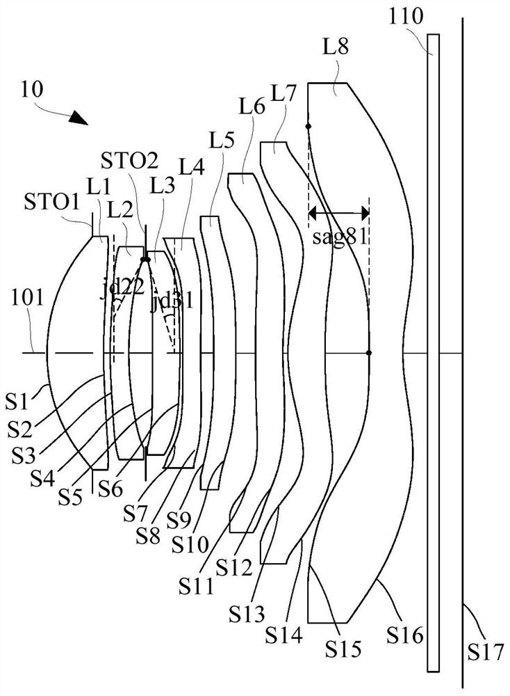
[0115] refer to figure 1, in the first embodiment, the optical system 10 sequentially includes an aperture stop STO1, a first lens L1 with positive refractive power, a second lens L2 with negative refractive power, and a vignetting lens along the optical axis 101 from the object side to the image side. Stop STO2, the third lens L3 with positive refractive power, the fourth lens L4 with negative refractive power, the fifth lens L5 with negative refractive power, the sixth lens L6 with negative refractive power, the first lens L6 with positive refractive power The seven lenses L7 and the eighth lens L8 with negative refractive power, and the surface shapes of the lenses of the optical system 10 are as follows:

[0116] The object side S1 of the first lens L1 is convex at the near optical axis, and the image side S2 is concave at the near optical axis; the object side S1 is concave near the maximum effective aperture, and the image side S2 is convex near the maximum effective ape...

no. 2 example

[0149] refer to image 3 , in the second embodiment, the optical system 10 sequentially includes an aperture stop STO1, a first lens L1 with positive refractive power, a second lens L2 with negative refractive power, and a vignetting lens along the optical axis 101 from the object side to the image side. Stop STO2, the third lens L3 with positive refractive power, the fourth lens L4 with negative refractive power, the fifth lens L5 with positive refractive power, the sixth lens L6 with negative refractive power, the first lens L6 with positive refractive power The seven lenses L7 and the eighth lens L8 with negative refractive power, and the surface shapes of the lenses of the optical system 10 are as follows:

[0150] The object side S1 of the first lens L1 is convex at the near optical axis, and the image side S2 is concave at the near optical axis; the object side S1 is concave near the maximum effective aperture, and the image side S2 is convex near the maximum effective a...

no. 3 example

[0168] refer to Figure 5 , in the third embodiment, the optical system 10 sequentially includes an aperture stop STO1, a first lens L1 with positive refractive power, a second lens L2 with negative refractive power, and a vignetting lens along the optical axis 101 from the object side to the image side. Stop STO2, the third lens L3 with positive refractive power, the fourth lens L4 with negative refractive power, the fifth lens L5 with positive refractive power, the sixth lens L6 with negative refractive power, the first lens L6 with positive refractive power The seven lenses L7 and the eighth lens L8 with negative refractive power, and the surface shapes of the lenses of the optical system 10 are as follows:

[0169] The object side S1 of the first lens L1 is convex at the near optical axis, and the image side S2 is concave at the near optical axis; the object side S1 is concave near the maximum effective aperture, and the image side S2 is convex near the maximum effective a...


PUM

PropertyMeasurementUnit
Effective focal lengthaaaaaaaaaa
Maximum viewing angleaaaaaaaaaa
Optical lengthaaaaaaaaaa

Abstract

The invention relates to an optical system, a camera module and electronic equipment. The optical system includes: a first lens element with positive refractive power having an object-side surface being convex in a paraxial region and an image-side surface being concave in a paraxial region; a second lens element with negative refractive power having an object-side surface being convex in a paraxial region and an image-side surface being concave in a paraxial region; a third lens; a fourth lens; a fifth lens element; a sixth lens element with negative refractive power having an image-side surface being concave in a paraxial region thereof; a seventh lens element with positive refractive power having an object-side surface being convex in a paraxial region thereof, both the object-side surface and the image-side surface being aspheric, and at least one of the object-side surface and the image-side surface being retroflexure; and an eighth lens element with negative refractive power, the image-side surface thereof being concave in a paraxial region thereof, both the object-side surface and the image-side surface being aspheric, and at least one of the object-side surface and the image-side surface being inflection, wherein the optical system satisfies the following relation: 2.5<f678/f6<8.5. The optical system can maintain good imaging quality while achieving miniaturization.

Description

technical field [0001] The invention relates to the technical field of photography and imaging, in particular to an optical system, a camera module and electronic equipment. Background technique [0002] With the rapid popularization of electronic devices such as smart phones, smart watches, and tablet computers in the consumer market, the camera performance of electronic devices has also attracted the market's attention. For example, the highlights of new product releases by well-known companies mostly revolve around the camera Performance unfolds. [0003] In order to improve the camera performance of the device, a multi-lens design is generally used to improve the imaging quality. However, with the increase in the number of lenses, various problems in the optical system gradually appear. For example, the increase in the number of lenses will increase the size of the system, and it is also easy to cause poor design of the refractive power of some lenses, resulting in incr...

Claims


Application Information

Patent Timeline
IPC IPC(8): G02B13/00G02B13/18
CPCG02B13/0015G02B13/0045
Inventor 杨健李明
Owner JIANGXI JINGCHAO OPTICAL CO LTD
Why Eureka
Try Eureka