Method for quickly positioning and measuring dead load condition of in-service bridge structure

A bridge structure, positioning measurement technology, applied in the field of bridge structure, can solve problems such as time-consuming, dependence on professional quality and subjective judgment, lack of quantitative scientific basis, etc., to improve the efficiency of measurement and control, and quickly calculate the structure size.

Pending Publication Date: 2021-07-23
中路高科交通检测检验认证有限公司 +1
View PDF6 Cites 1 Cited by
  • Summary
  • Abstract
  • Description
  • Claims
  • Application Information

AI Technical Summary

Problems solved by technology

But the disadvantages are also obvious. Apart from the disadvantages of high cost and long time-consuming, the main problem is that the inspection results largely depend on the observer's professional quality and subjective judgment, and lack of quantitative scientific basis.
However, the non-destructive testing radar method and shock echo method measure the thickness, and the error is at the centimeter level, which cannot meet the requirements of accurate calculation of structural size and dead load.
[0005] Therefore, how to accurately locate the segment with complex spatial shape of the bridge, and then quickly calculate the structural size, and judge the rationality of the overall design of the bridge in service, there is no good method at present

Method used


Image

  • Method for quickly positioning and measuring dead load condition of in-service bridge structure
  • Method for quickly positioning and measuring dead load condition of in-service bridge structure
  • Method for quickly positioning and measuring dead load condition of in-service bridge structure

Examples


Embodiment Construction

[0028] The following is attached Figure 1-9 The present invention is described in further detail.

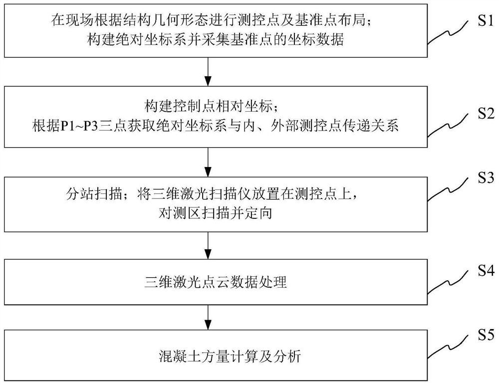
[0029] refer to figure 1 As shown, the embodiment of the present invention provides a method for quickly locating and measuring the dead load condition of an in-service bridge structure using three-dimensional laser scanning technology combined with local scale measurement, including the following steps;

[0030] S1. On-site layout of measurement and control points and reference points according to the structural geometry; the measurement and control points include: external measurement and control points of the structure and internal measurement and control points of the structure; the reference points are three absolute references arranged at preset distances around the adjacent structure Points P1~P3, based on the total station to construct an absolute coordinate system (OXYZ) for the three absolute reference points P1~P3 A , and collect the coordinate data of three absolu...


PUM


Abstract

The invention discloses a method for quickly positioning and measuring the dead load condition of an in-service bridge structure. The method specifically comprises the following steps of: performing layout of measurement and control points and reference points on site according to the geometric morphology of the structure; constructing an absolute coordinate system based on a total station and collecting coordinate data of the reference points; constructing relative coordinates of measurement and control points; according to the absolute reference points P1-P3, obtaining a transmission relation between the absolute coordinate system and the internal and external measurement and control points; a three-dimensional laser scanner is placed on a measurement and control point, and segmented scanning and orientation are carried out on the measurement and control point; performing data processing on the three-dimensional laser point cloud according to point cloud cutting and noise data elimination; an ideal three-dimensional point cloud model is obtained based on data processing, and the volume of concrete is calculated and analyzed. According to the method, accurate positioning can be carried out on internal and external spaces of the bridge, so that the structure size is quickly calculated, the rationality of the overall design of the in-service bridge is judged, and the measurement and control efficiency of influence of dead load variation of the bridge structure on the technical state of the service period of the structure is improved.

Description

technical field [0001] The invention belongs to the field of bridge structures, and relates to a method for rapidly positioning and measuring the dead load status of in-service bridge structures by using three-dimensional laser scanning technology combined with local scale measurement, in particular to a method for using a three-dimensional laser scanner to measure prestressed concrete box girders A method for rapid positioning and measurement of dead load condition of continuous rigid frame bridge structure. Background technique [0002] At present, domestic long-span continuous rigid frame bridges mainly suffer from two major problems: excessive deflection in the middle span of the main span and cracks in the box girder body. The stiffness is further reduced, and the mid-span deflection is further aggravated. The two interact to form a vicious circle. The long-term deformation and cracking of long-span concrete beam bridges are related to the safety and durability of the b...

Claims


Application Information

Patent Timeline
Patent Type & Authority Applications(China)
IPC IPC(8): G06F30/15G06F30/20G06T17/00G06F119/14
CPCG06F30/15G06F30/20G06T17/00G06F2119/14
Inventor 姜震宇解会兵杨镇吉蔺宝垚刘昭
Owner 中路高科交通检测检验认证有限公司
Why Eureka
Try Eureka