Visual target spot arrangement method based on laser radar grid map coupling

A grid map and laser radar technology, applied in image enhancement, image analysis, measuring devices, etc., can solve the problems of lack of visual target system utilization, confinement, and AGV's inability to achieve high-precision self-positioning on grid maps, and achieve Fewer coupling measurements, improved positioning accuracy, and high coupling solution accuracy

Pending Publication Date: 2021-07-23
NANJING UNIV OF AERONAUTICS & ASTRONAUTICS
View PDF0 Cites 1 Cited by
  • Summary
  • Abstract
  • Description
  • Claims
  • Application Information

AI Technical Summary

Problems solved by technology

The existing visual targets are limited to two-dimensional codes, and the lack of systematic utilization of visual targets makes it impossible for AGVs to achieve high-precision self-positioning effects in grid maps

Method used


Image

  • Visual target spot arrangement method based on laser radar grid map coupling
  • Visual target spot arrangement method based on laser radar grid map coupling
  • Visual target spot arrangement method based on laser radar grid map coupling

Examples


Embodiment Construction

[0042] The present invention will be further described below in conjunction with the accompanying drawings and embodiments. It should be understood that the specific embodiments described here are only used to explain the present invention, and are not intended to limit the present invention.

[0043] Such as Figure 1-3 shown.

[0044] A visual target layout method based on laser radar grid map coupling, including the following two aspects:

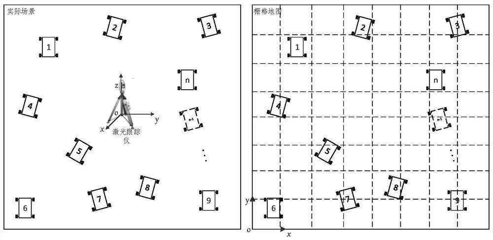
[0045] 1.1 Design a method of introducing laser tracker measurement equipment to realize the coupling of the grid map coordinate system constructed by laser radar and the laser tracker coordinate system (that is, the actual scene coordinate system);

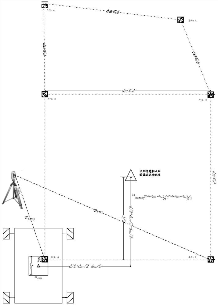
[0046] 1.2 Research a visual target layout method based on the analysis of coordinate coupling uncertainty, measurement uncertainty and motion uncertainty.

[0047] The grid map coordinate system and the laser tracker coordinate system (that is, the actual scene coordinate system) couplin...


PUM


Abstract

A visual target spot arrangement method based on laser radar grid map coupling is characterized in that firstly, laser tracker measuring equipment is introduced, and coupling of a grid map coordinate system constructed by a laser radar and a laser tracker coordinate system is achieved; secondly, based on the coordinate coupling uncertainty, the measurement uncertainty and the motion uncertainty, the arrangement of the visual target spots is determined; according to the invention, the precision of coordinate system coupling and target spot arrangement is improved; coordinate system coupling measurement times are few, the coupling calculation precision is high, visual targets are flexibly laid in combination with an actual aeronautical manufacturing scene, the method is flexible and robust, the method can be widely applied to the field of aeronautical manufacturing, and after the visual targets are fused into the grid map, AGV navigation positioning precision can be effectively improved.

Description

technical field [0001] The present invention relates to an aviation manufacturing technology, in particular to a laser radar grid map coupling and visual target point layout method applied in the field of aviation manufacturing, specifically a visual target point based on laser radar grid map coupling Layout method. Background technique [0002] At present, the grid map used by AGV in the aviation manufacturing field is constructed with the help of lidar SLAM technology. Due to the limitations of sensors and algorithms, the accuracy of the grid map is low. In addition, there is a lack of methods for accurately coupling the grid probability map with the actual scene. The coupling accuracy of the existing AMCL probability method for coupling the map is low, which cannot meet the needs of high-precision navigation and positioning. [0003] Under the background of Industry 4.0, the field of aviation manufacturing has ushered in rapid development. With the advancement of in-sit...

Claims


Application Information

Patent Timeline
Patent Type & Authority Applications(China)
IPC IPC(8): G06F30/18G06F30/20G06T7/30G06T7/70G01S17/89
CPCG01S17/89G06T2207/10028G06T2207/30252G06T7/30G06T7/70G06F30/18G06F30/20
Inventor 李泷杲黄翔黄智超李根曾琪齐凯陶克梅
Owner NANJING UNIV OF AERONAUTICS & ASTRONAUTICS
Why Eureka
Try Eureka