Laying device and method for high-voltage cable with special-shaped lumen

A technology of high-voltage cables and special-shaped tubes, which is applied in the field of high-voltage cable laying devices with special-shaped lumens, and can solve problems such as reducing laying time and cost, and inconvenient bending of power cables

Active Publication Date: 2022-05-27
POWERCHINA SEPCO1 ELECTRIC POWER CONSTR CO LTD
View PDF6 Cites 0 Cited by
  • Summary
  • Abstract
  • Description
  • Claims
  • Application Information

AI Technical Summary

Problems solved by technology

[0005] In view of the deficiencies in the prior art, the purpose of the present invention is to provide a special-shaped lumen high-voltage cable laying device and method, which adopts a specially set clamping mechanism and a pipe matched with the clamping mechanism, and the clamping mechanism runs along the pipeline It can drive the power cable to bend in the pipe, which can solve the problem that the existing power cable is not easy to bend, and reduce the laying time and cost

Method used


Image

  • Laying device and method for high-voltage cable with special-shaped lumen
  • Laying device and method for high-voltage cable with special-shaped lumen
  • Laying device and method for high-voltage cable with special-shaped lumen

Examples


Embodiment 1

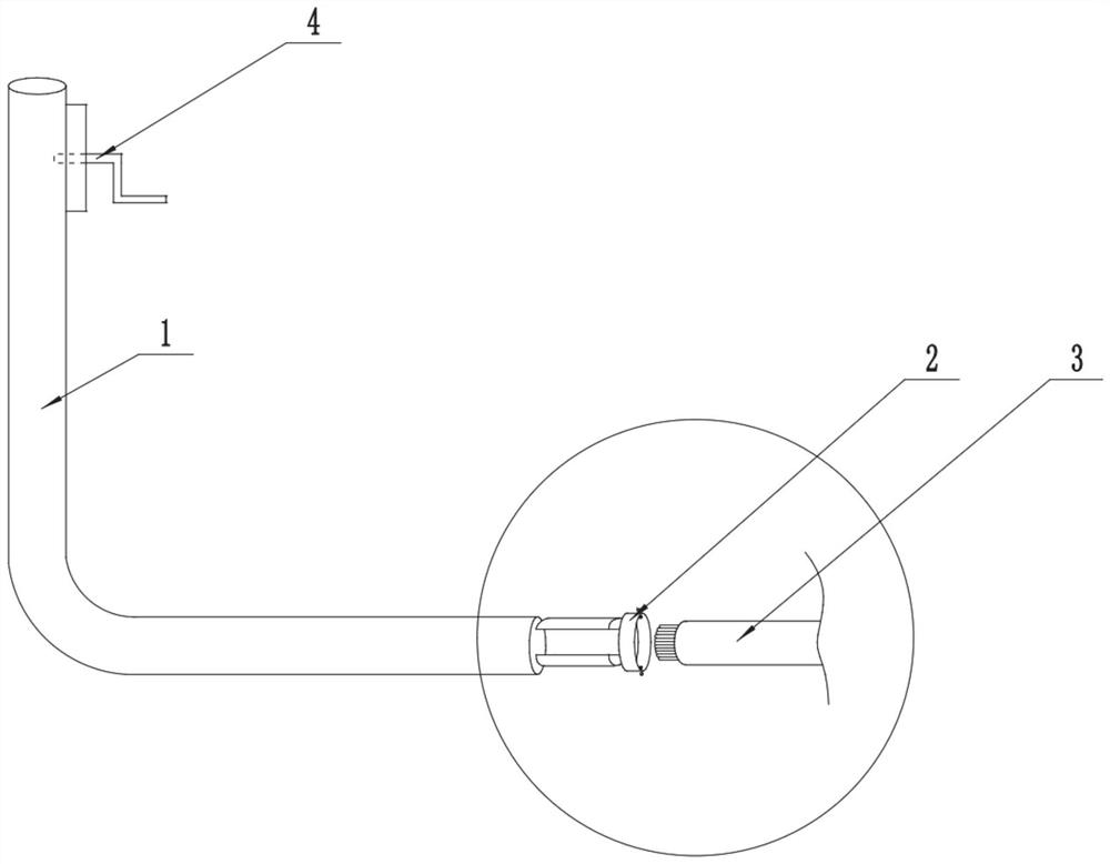
[0028] In a typical implementation of the present invention, this embodiment discloses a special-shaped lumen high-voltage cable laying device, including a pipe 1 and a clamping mechanism 2, the clamping mechanism 2 is arranged inside the pipe 1, and the clamping mechanism 2 can The inner wall of the pipe 1 is in contact; the end of the pipe 1 is provided with a handle, and the handle is connected to the clamping mechanism 2 through a traction cable (not shown in the figure), and the pipe 1 can be bent. For the inner bending section 12 and the outer bending section 12, the clamping mechanism 2 is provided with at least two arc-shaped pieces that are in contact with the inside of the pipe 1, and one of the arc-shaped pieces is located on one side of the inner bending section 12 of the pipe 1, wherein The other arc-shaped part is located on the side of the outer bending section 12 of the pipe 1 .

[0029] More specifically, in this embodiment, the pipe 1 is made of PPR material,...

Embodiment 2

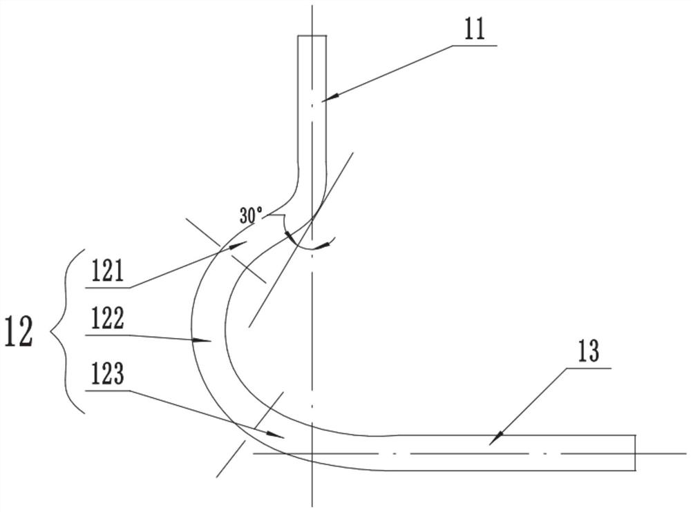
[0055] In an exemplary embodiment of the present invention, as image 3 As shown, this embodiment discloses a special-shaped lumen high-voltage cable laying device. The difference from Embodiment 1 is that in this embodiment, the shape of the bending section 12 of the pipe 1 is different from that in Embodiment 1.

[0056] It should be noted that, in this embodiment, the plane passing through the central axis of the vertical section 11 and perpendicular to the horizontal section 13 is defined as the reference plane, the side of the reference plane away from the horizontal section 13 is the outside, and the side close to the horizontal section 13 is inside.

[0057] like image 3 As shown, in this embodiment, the bending section 12 is divided into a first bending part 121 , a first bending part 122 and a third bending part 123 which are connected to each other, wherein one end of the first bending part 121 is connected to The vertical section 11, the other end is connected to...

Embodiment 3

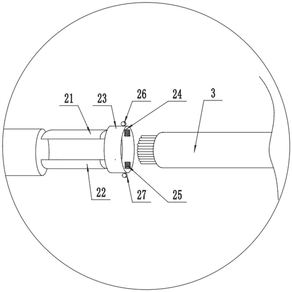
[0062] In a typical implementation of the present invention, this embodiment discloses a special-shaped lumen high-voltage cable laying device. The difference from Embodiment 1 is that the roller is replaced with a protrusion provided on the annular member 23 .


PUM


Abstract

The invention discloses a device and method for laying high-voltage cables with special-shaped lumens, which belong to the technical field of cable construction. A specially arranged clamping mechanism and a pipe matched with the clamping mechanism are adopted. The clamping mechanism can drive power when running along the pipeline. The cable is bent in the pipe, which can solve the problem that the existing power cable is not easy to bend, and reduces the laying time and cost. The device includes a pipe and a clamping mechanism. The clamping mechanism is located inside the pipeline. The inner wall of the pipe is in contact; the end of the pipe is provided with a handle, and the handle passes through the pipe wall of the pipe. The wall is arc-shaped, and the traction cable can be attached to the inner pipe wall of the bending section to slide.

Description

technical field [0001] The invention belongs to the technical field of cable construction, and in particular relates to a special-shaped lumen high-voltage cable laying device and method. Background technique [0002] Power cables refer to cables with large diameters, generally 3 or 4 cores, with thick interphase insulation and metal armor protection on the outside. They are mainly used in power supply systems as the backbone of three-phase industrial power or single-phase civil power. [0003] Cable faults caused by mechanical damage account for a large proportion of cable faults. Mechanical damage is easily caused during power cable construction. The cable is pulled due to excessive mechanical tension, and the cable is damaged due to excessive bending of the cable. Some mechanical damages are very slight. Causes a malfunction, and the damaged part develops into a malfunction after several months or even 1-2 years of use. The shape of the power cable is relatively sturdy. ...

Claims


Application Information

Patent Timeline
Patent Type & Authority Patents(China)
IPC IPC(8): H02G1/08
CPCH02G1/081
Inventor 庞继勇王文斌马丕地
Owner POWERCHINA SEPCO1 ELECTRIC POWER CONSTR CO LTD
Why Eureka
Try Eureka