

Apparatus for heat treatment of motor vehicles or motor vehicle parts
A technology for motor vehicles and components, applied in the field of killing pests, can solve the problems of high investment, long construction law permitting time, etc., and achieve the effect of high energy efficiency, saving capital cost, and efficient storage
- Summary
- Abstract
- Description
- Claims
- Application Information
AI Technical Summary
Problems solved by technology
Method used
Image

Examples
Embodiment Construction
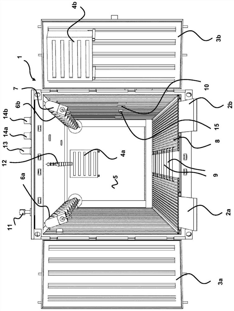
[0034] figure 1 The device according to the invention is shown in the state in which the loading port of the isolated sea container 1 is opened and the loading ramps 2a and 2b are folded out. Motor vehicles, which are to be heat-treated, for example to kill vermin, can be rolled into the container interior via the loading ramps 2a, 2b. After the loading ramps 2a and 2b have been turned upwards, the loading opening can be closed by pivoting the two flaps 3a and 3b. When the loading port is closed, a unit 4a, 4b is respectively arranged at the two end sides of the interior of the container 1, in which unit a heat exchanger and a fan are respectively integrated. On the end side of the interior of the container 1 opposite the loading opening there is a transverse wall 5 behind which there is a cooling unit, not shown, surrounding two fans. The cooling unit, not shown in this figure, forms a vertical well. The rear wall of the cooling unit functionally complements the wall of th...
PUM
 Abstract
Description
Claims
Application Information