Pressure medium-operated cabin brake and valve arrangement for controlling the emergency brake function of the pressure medium-operated cabin brake of a lift system

A pressure medium, emergency braking technology, used in elevators, lifting equipment in mines, transportation and packaging, etc., can solve the problem of not knowing the combination of spring-mass-system, and achieve the effect of reliable braking force

Active Publication Date: 2021-07-23
CHRISTIAN MAYR GMBH & CO KG
View PDF15 Cites 0 Cited by
  • Summary
  • Abstract
  • Description
  • Claims
  • Application Information

AI Technical Summary

Problems solved by technology

The exact details of how the spring-mass-system is incorporated

Method used


Image

  • Pressure medium-operated cabin brake and valve arrangement for controlling the emergency brake function of the pressure medium-operated cabin brake of a lift system
  • Pressure medium-operated cabin brake and valve arrangement for controlling the emergency brake function of the pressure medium-operated cabin brake of a lift system
  • Pressure medium-operated cabin brake and valve arrangement for controlling the emergency brake function of the pressure medium-operated cabin brake of a lift system

Examples


Embodiment Construction

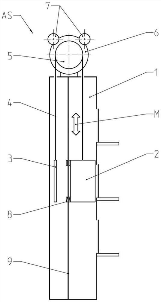
[0032] exist figure 1 shows the principle construction of an elevator according to the prior art in a guide wheel configuration with a rope transmission ratio of 1:1. A passenger cabin (2) and a counterweight (3) are arranged in the elevator shaft (1) and are connected to each other via a spreader (4). The spreader (4), which may consist of a rope set or a belt, is deflected by and frictionally engaged with guide wheels (5). The vertical movement of the cabin (2) and the counterweight (3) in the elevator shaft (1) in the direction of travel (M) is achieved by rotating a guide wheel (5) connected to the motor.

[0033] In passenger lifts according to the prior art, in order to ensure the braking and stopping of the cabin (2) and the counterweight (3), there are two braking systems independent of each other:

[0034] - a first brake system (7) acting directly on the brake disc (6) connected to the guide wheel (5) and in this example for redundancy purposes the first brake syst...


PUM


Abstract

The invention proposes a pressure medium-operated cabin brake for a lift system and also, for controlling said cabin brake, a valve arrangement with integrated control of the deceleration of the cabin during emergency braking operations. According to the invention, a spring-mass control valve or a proportional solenoid valve which is activated by an acceleration sensor is integrated into the valve arrangement for controlling the deceleration. The control arrangement is designed such that the deceleration of the cabin always lies within prespecified limit values. In addition, the brake springs and the pistons of the cabin brake and also the pressures in the valve arrangement are matched to one another such that a sufficient braking force for decelerating and holding the cabin is always available during emergency braking operations.

Description

technical field [0001] The invention relates to a brake, a valve assembly and a method for actuating a pressure-medium-operated brake, preferably for a passenger lift. Background technique [0002] In known elevator systems, an elevator cabin arranged in the elevator shaft moves vertically, the elevator cabin being connected to a counterweight via a spreader. For this purpose, the counterweight is generally set to correspond to the mass of the half-loaded elevator cabin. The vertical movement of the elevator cabin and the counterweight is achieved by the spreader encircling and frictionally engaging a guide wheel located mostly at the upper end of the elevator shaft and connected to the drive motor. [0003] This type of lift system, also known as a pulley lift, is usually equipped with 2 brake systems that are independent of each other. [0004] - The first brake system acting directly on the guide pulley serves as a running and emergency brake. In normal operation, the ...

Claims


Application Information

Patent Timeline
IPC IPC(8): B66B5/18
CPCB66B5/18B66B17/34
Inventor M·赫克特J·胡贝尔M·赖希勒
Owner CHRISTIAN MAYR GMBH & CO KG
Why Eureka
Try Eureka