Brake assembly and method for controlling brake assembly

A technology of brake components and brake discs, which is applied in the direction of brake components, brake transmission devices, and axially engaged brake parts, etc., and can solve problems such as damage to wheel brake parts

Active Publication Date: 2021-07-23
KNORR-BREMSE SYST FUER NUTZFAHRZEUGE GMBH
View PDF7 Cites 3 Cited by
  • Summary
  • Abstract
  • Description
  • Claims
  • Application Information

AI Technical Summary

Problems solved by technology

[0003] It has been found that in the event of a malfunction or loss of power, particularly when the wheel brake actuators are operating at high speeds, damage to the wheel brake components may occur

Method used


Image

  • Brake assembly and method for controlling brake assembly
  • Brake assembly and method for controlling brake assembly

Examples


Embodiment Construction

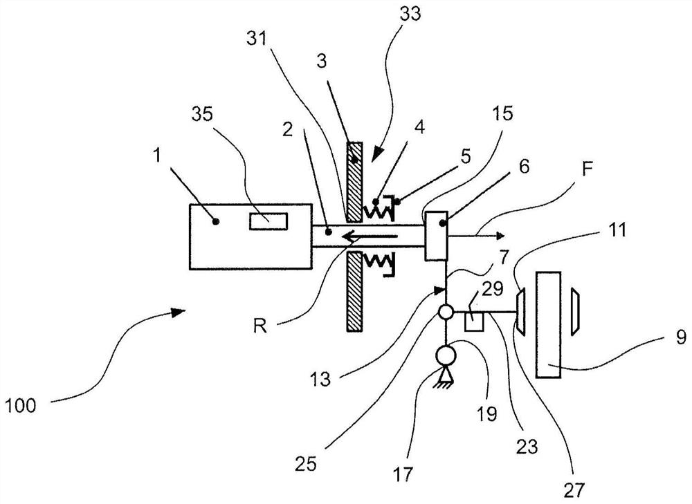
[0028] exist figure 1 , the active braking operation of the brake assembly is also shown. During a braking operation, the brake pads 11 are in frictional engagement with the brake disc 9 which is in rotational engagement with a wheel (not shown) of the vehicle. During a braking operation, a clamping force is exerted on the brake disc 9 by the brake pads 11 . Actuation of the brake pads 11 is achieved by means of a lever arrangement 13 . The lever arrangement 13 is coupled to the output shaft 2 which can be actuated by the actuator 1 . The lever arrangement 13 can be positively and / or force-fittingly coupled to the output shaft 2 via a coupling member 6 arranged at the distal end 15 of the output shaft 2 . The lever arrangement 13 comprises a pivot member 7 pivotably mounted with one end 19 of the rod 7 on a mount 17, usually fixedly arranged to the chassis of the vehicle (not shown) . At the other end 21 of the rod 7 , arranged diametrically opposite to the end 19 , the r...


PUM


Abstract

The present invention relates to a brake assembly comprising a brake disc in rotational engagement with a wheel of a vehicle, a brake pad which frictionally engages said brake disc when an actuator force is applied thereto, an actuator having an output shaft driven in a forward direction and a reverse direction in order to bring the brake pad and brake disc in said frictional engagement, and an energy absorption and / or storage unit absorbing forces acting on the output shaft in the reverse direction in case of a predetermined operation situation.

Description

technical field [0001] The invention relates to a brake assembly. Furthermore, the invention also provides a method for controlling a brake assembly. Background technique [0002] In general, actuators for vehicle wheel brakes present two main challenges. Firstly, wheel brake actuators, in particular using electromechanical principles, are associated with very large inertias, ie stopping energies in their actuation end positions. Secondly, wheel brake actuators have to perform highly dynamic actuation movements, especially due to the increased vehicle weight and increased requirements for braking efficiency. [0003] It has been found that in the event of a malfunction or loss of power, particularly when the wheel brake actuators are operating at high speeds, damage to the wheel brake components may occur. For example, in the event of a malfunction or loss of power, the output shaft connected to the actuator, which is used to achieve the actuation The frictional engageme...

Claims


Application Information

Patent Timeline
Patent Type & Authority Applications(China)
IPC IPC(8): F16D65/18B60T13/74
CPCB60T13/741F16D61/00F16D65/18F16D2121/24F16D55/226B60T1/065B60T13/746F16D65/005F16D65/40F16D2125/64
Inventor J·绍博M·布莱辛R·特里姆普W·帕勒M·克林格纳A·布赫A·塞伯斯H·内梅特C·科克雷尔V·蒂哈尼C·姆利纳克塞克
Owner KNORR-BREMSE SYST FUER NUTZFAHRZEUGE GMBH
Why Eureka
Try Eureka