Movable electro-hydraulic composite drive spraying robot with large working space

A spraying robot and electro-hydraulic composite technology, applied in the field of robots, can solve problems such as the limitation of the running space by the track, the interference of the spraying process, and the limitation of the working space, so as to improve the spraying accuracy and dynamic performance, improve the motion stability, and improve the applicability Effect

Active Publication Date: 2021-07-27
HEFEI UNIV OF TECH
View PDF11 Cites 6 Cited by
  • Summary
  • Abstract
  • Description
  • Claims
  • Application Information

AI Technical Summary

Problems solved by technology

However, when the existing flexible cable drive mechanism faces complex surfaces, the drive cable easily interferes with the workpiece to be processed, which interferes with the spraying process
For example, the Chinese invention patent with the application number 202010243575.1: a cable-driven hybrid spraying robot mechanism and its operation method. The main body of the mechanism is driven by a rope and has the advantages of a large working space. The end spray gun is not flexible enough, and there may be interference between the driving rope and the workpiece at the same time; the Chinese invention patent with the application number 201910641158. The orbit is limited, and the actual movement form of its end is close to the series mechanical arm, and its working space is limited to a certain extent; the Chinese invention patent with the application number CN201811064098.1: a rope traction parallel spraying robot on the outer surface of the hull, the mechanism is mainly for The curved surfaces on both sides of the ship have relatively low flexibility at the end, and the mechanism is not universal

Method used


Image

  • Movable electro-hydraulic composite drive spraying robot with large working space
  • Movable electro-hydraulic composite drive spraying robot with large working space
  • Movable electro-hydraulic composite drive spraying robot with large working space

Examples


Embodiment Construction

[0077] The specific embodiments of the present invention are given below, and will be described in conjunction with the accompanying drawings.

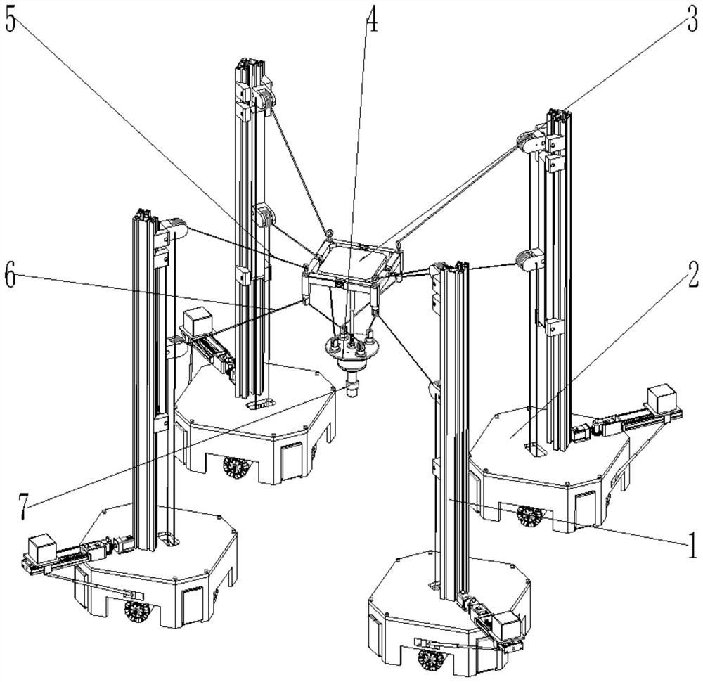
[0078] Combine figure 1 The spray robot with large working space removable electro-hydraulic composite drive is adjusted by four identical drive rope position adjustment modules 1, four exact same mobile base 2, adjustable auxiliary sports platform 3, rotary moving platform 4 , Four adjustable auxiliary sports platforms drive rope 5, four swivel moving platforms drive rope 6, and the gun 7 is composed.

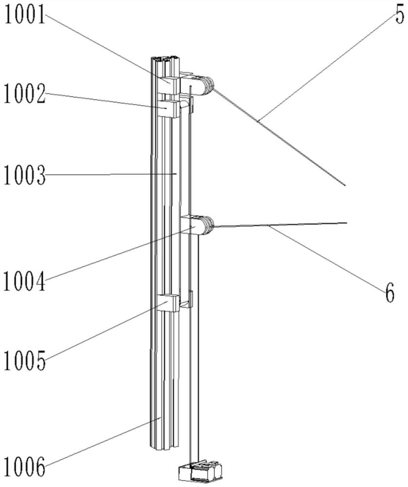
[0079] Further, four mobile base 2 is responsible for carrying other mechanisms, securing the corresponding four drive rope adjustment modules 1, the corresponding four drive rope adjustment module 1 is fixed to the mobile base 2 by the mounting holes reserved on the mobile base 2. On, thereby realizing a large-range movement of the robot's overall movement; the adjustable auxiliary motion platform drive rope 5 is driven by one motor in t...


PUM


Abstract

The invention discloses a movable electro-hydraulic composite drive spraying robot with a large working space. The movable electro-hydraulic composite drive spraying robot comprises a plurality of movable bases, the movable bases are matched with one another and are used for bearing drive rope adjusting modules, profile struts in the drive rope adjusting modules are respectively fixed on the movable bases, an operation space is defined by the multiple movable bases, a movable adjustable auxiliary motion platform is erected in the operation space, a rotary motion platform is arranged below the adjustable auxiliary motion platform, the adjustable auxiliary motion platform is connected with the rotary motion platform through a hydraulic push rod, a spray gun is installed on the bottom end face of the rotary motion platform, and a balance mechanism and a fixed supporting mechanism which are used for balancing the traction force of a rope and maintaining the balance of the mechanism are further installed on the movable bases. The movable electro-hydraulic composite drive spraying robot is reasonable in structural design, multi-degree-of-freedom movement in a large working space is achieved, meanwhile, interference between a traction rope and a machined workpiece is avoided, and the applicability of equipment is improved.

Description

Technical field: [0001] The present invention relates to the field of robots, mainly involving a movable electro-hydraulic composite drive spraying robot having a large working space. Background technique: [0002] Spray can bring rust, anti-corrosion, and other advantages to the machining workpiece, and can improve its appearance, which has become an indispensable process flow in all walks of life. In traditional industrial production, it is mainly used to operate the operation of artificial spraying. However, artificial spraying will bring a certain damage to workers, and the work efficiency is low, and the quality of spray is also difficult to guarantee. Therefore, the spraying robot is constantly replacing traditional artificial spraying to achieve production efficiency and ensure the purpose of stable product quality. [0003] The existing spraying robot is mainly based on a series of rigid robots. It is used to install a spray gun on the series robot. Its positioning accura...

Claims


Application Information

Patent Timeline
Patent Type & Authority Applications(China)
IPC IPC(8): B05B13/02B05B13/04B25J11/00
CPCB05B13/0221B05B13/0431B25J11/0075
Inventor 訾斌赵嘉浩钱森王正雨徐锋潘敬锋周斌姜姗姗李元
Owner HEFEI UNIV OF TECH
Why Eureka
Try Eureka