Continuous feeding, stirring and friction additive manufacturing device and additive manufacturing method thereof

A technology of additive manufacturing, feeding and mixing, applied in the direction of manufacturing tools, additive processing, non-electric welding equipment, etc., can solve the problems of continuous feeding and feeding, easy generation of additive layer, interruption and restart, etc., to improve production efficiency , increase the connection width, and have a wide range of applications

Active Publication Date: 2021-07-27
HARBIN INST OF TECH
View PDF13 Cites 8 Cited by
  • Summary
  • Abstract
  • Description
  • Claims
  • Application Information

AI Technical Summary

Problems solved by technology

[0006] In view of this, the present invention aims to propose a continuous feeding and feeding friction stir additive manufacturing device and additive manufacturing method, breaking through the traditional friction stir additive technology, which is difficult to continuously feed and feed materials, and the additive process requires layer-by-layer clamping, increasing Defects are easy to occur between material layers, and the technical status of secondary processing and material reduction after material addition solves the difficult problem of interruption and restart of the existing continuous feeding strategy

Method used


Image

  • Continuous feeding, stirring and friction additive manufacturing device and additive manufacturing method thereof
  • Continuous feeding, stirring and friction additive manufacturing device and additive manufacturing method thereof
  • Continuous feeding, stirring and friction additive manufacturing device and additive manufacturing method thereof

Examples


Embodiment Construction

[0049] It should be noted that, in the case of no conflict, the embodiments of the present invention and the features in the embodiments can be combined with each other.

[0050] The present invention will be described in detail below with reference to the accompanying drawings and examples.

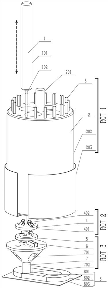
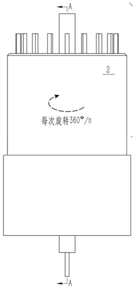
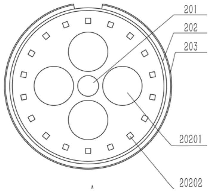
[0051] Such as Figure 1-10 As shown, a continuous feeding and feeding friction stir additive manufacturing device includes a hydraulic ejector mechanism 1, a disc feeding mechanism 2, an upper clutch module 4, a lower clutch module 5, and a constant speed feeding mechanism 6 arranged from top to bottom. , an additive mixing head 7 and an additive manufacturing component 8, a plurality of additive raw materials 3 with a square cross-section are evenly arranged in the disc feeding mechanism 2, and the lower clutch module 5 is fixed on the constant speed feeding mechanism 6, and the The constant-speed feeding mechanism 6 is fixed on the additive mixing head 7, the disc feeding mechanism 2...


PUM


Abstract

The invention provides a continuous feeding, stirring and friction additive manufacturing device and an additive manufacturing method thereof. The device comprises a hydraulic ejector rod mechanism, a disc type feeding mechanism, an upper clutch module, a lower clutch module, a constant-speed feeding mechanism, an additive stirring head and an additive manufacturing component which are arranged from top to bottom; a plurality of additive raw materials are evenly arranged in the disc type feeding mechanism, the disc type feeding mechanism replaces the next additive raw material under the condition that the disc type feeding mechanism does not stop rotating, the two clutch modules are matched to guide the new additive raw material and the previous additive raw material to be introduced into the additive stirring head in a phase synchronization mode, and the hydraulic ejector rod mechanism pushes the new additive raw material to be introduced into the upper clutch module; and the constant-speed feeding mechanism drives the additive raw materials to move downwards, and the stirring head drives the additive raw materials to rotate and perform friction thermal plasticizing deposition with the additive manufacturing component, so that continuous feeding additive manufacturing is achieved. The device breaks through the current situations that continuous feeding of traditional stirring friction material increase is difficult, layer-by-layer clamping is needed, defects are prone to being generated, and secondary machining is needed after material increase, and solves the problem that interruption restarting is difficult.

Description

technical field [0001] The invention belongs to the technical field of solid-phase additive manufacturing, and in particular relates to a continuous feeding and feeding friction stirring additive manufacturing device and an additive manufacturing method. Background technique [0002] Additive manufacturing technology, commonly known as 3D printing technology, is a digital manufacturing technology that achieves moldless and precise forming of components by adding and accumulating materials layer by layer. It manufactures three-dimensional complex shape components into simple two-dimensional planar shapes. It avoids a large amount of material and energy waste in traditional machining and precise forming manufacturing, and provides a new design idea for the realization of high-performance or super-performance key components. At the same time, this technology can greatly shorten the production cycle, reduce production costs and processing and manufacturing costs, making it possi...

Claims


Application Information

Patent Timeline
Patent Type & Authority Applications(China)
IPC IPC(8): B23K20/12B23K20/26B33Y10/00B33Y30/00
CPCB23K20/1245B23K20/122B33Y30/00B33Y10/00
Inventor 黄永宪谢聿铭孟祥晨
Owner HARBIN INST OF TECH
Why Eureka
Try Eureka