
Cable detection equipment

A testing equipment and cable technology, applied in the field of cable testing equipment, can solve the problems of low testing efficiency, poor versatility of cable testing equipment, high labor cost, improve testing efficiency, realize fully automated testing and data control, The effect of reducing labor costs

Pending Publication Date: 2021-07-27
昆山威典电子有限公司
View PDF8 Cites 0 Cited by
  • Summary
  • Abstract
  • Description
  • Claims
  • Application Information

AI Technical Summary

Problems solved by technology

[0004] The purpose of the present invention is to provide a cable detection device to solve the technical problems of poor versatility, low test efficiency and high labor cost in the prior art.

Method used


Image

  • Cable detection equipment
  • Cable detection equipment
  • Cable detection equipment

Examples


Embodiment 1

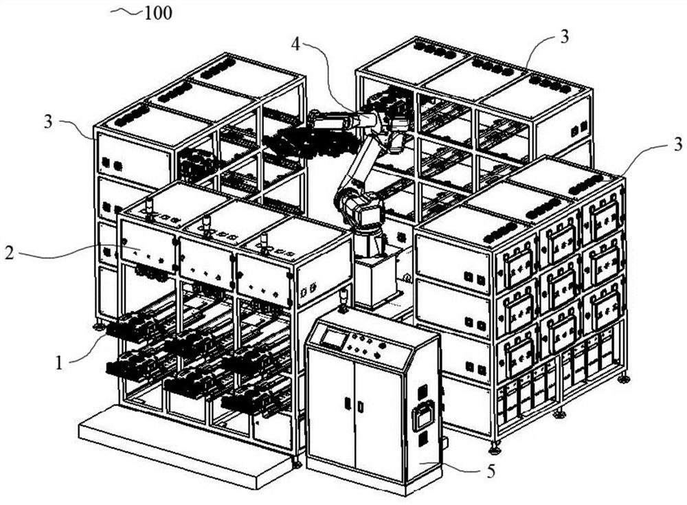
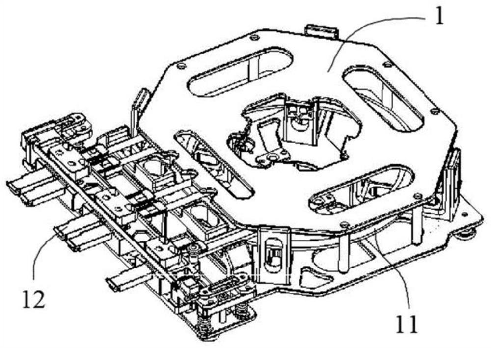
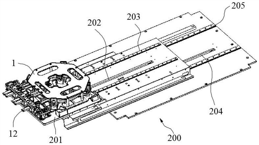
[0039] Such as figure 1 As shown, this embodiment provides a cable detection device, which includes: a carrier 1, an operating table 2, a detection device, a manipulator 4, and a controller 5. During specific use, the staff can place the device to be tested The carrier 1 of the cable is placed on the operating table 2, and then the controller 5 can set the program, and the carrier 1 on which the cable to be tested is placed is moved to the detection device by controlling the manipulator 4, and the detection device tests the cable to be tested. With different transmission characteristics, various testing processes of the cable 11 are completed. After the detection device completes the test, the detection device collects the test data, and the manipulator 4 returns the carrier 1 with the tested cable to the operating table 2, and the staff The work of recovering the carrier 1 of the tested cable is completed at the operating table 2, and the test work of the cable 11 is complete...

Embodiment 2

[0055] This embodiment provides a cable detection device, which is different from Embodiment 1 in that: the cable detection device in this embodiment includes a detection device, and the detection device includes a detection mechanism 3, and the detection mechanism 3 is arranged in parallel with the console 2 , the manipulator 4 is arranged in the middle position between the detection mechanism 3 and the operating platform 2 .

[0056] Preferably, the above-mentioned detection mechanism 3 includes a plurality of test stations 300, and the plurality of test stations 300 include one or more test units 304 and transmission units. The detection mechanism 3 in this embodiment includes nine test stations 300 as For example, each of the nine test stations 300 includes a test unit 304 and a transmission unit, and each test unit 304 is configured to detect a transmission characteristic of a cable 11 , and each transmission characteristic is different from each other.

[0057] Further, ...


PUM


Abstract

The invention relates to the technical field of electronic equipment detection, and particularly discloses cable detection equipment which comprises a carrier, an operation table, a detection device, a mechanical arm and a controller. When the cable detection equipment is used, a worker enables the mechanical arm through the controller to move the carrier on which a to-be-tested cable is placed on the operation table to the detection device; and the detection device tests different transmission characteristics of a to-be-tested cable and completes various test processes of the cable, after the detection device completes the test, the detection device collects test data, the mechanical arm puts the carrier on which the tested cable is placed back to the operation table, and a worker completes the recovery work of the carrier on the operation table. The cable detection equipment provided by the invention has multiple cable testing functions, is high in universality, is suitable for testing most cables in the market, can complete the cable testing work only by controlling the mechanical arm and the detection device through the controller in the whole testing process, and is high in testing efficiency.

Description

technical field [0001] The invention relates to the technical field of electronic equipment detection, in particular to a cable detection device. Background technique [0002] Cables are an important part of electronic equipment, so the demand for cables in the market is increasing day by day. All finished cables need to be tested before leaving the factory to check whether the cables meet the quality requirements. In traditional In the cable detection equipment, only a certain transmission characteristic of a certain cable to be tested can be tested, which has poor versatility and low test efficiency. Moreover, most of the current cable detection equipment needs to be manually removed / disconnected from the cable. For release and transportation work, the controllability of the detection process is not strong, and human interference is relatively large. [0003] Therefore, there is an urgent need for a cable detection device to solve the above technical problems. Contents ...

Claims


Application Information

Patent Timeline
IPC IPC(8): G01R31/00
CPCG01R31/00
Inventor 郑建生甄华全
Owner 昆山威典电子有限公司
Learn More