Fuel cell driven by hydrogen energy and fixing structure thereof
A fuel cell and fixed structure technology, which is applied in the direction of fuel cells, circuits, electrical components, etc., can solve the problems of increased system risk, increased pipeline flow resistance, complex layout, etc., and achieves high humidification intensity, high humidification efficiency, and uniform humidification Effect
- Summary
- Abstract
- Description
- Claims
- Application Information
AI Technical Summary
Problems solved by technology
Method used
Image
Examples
Embodiment 1
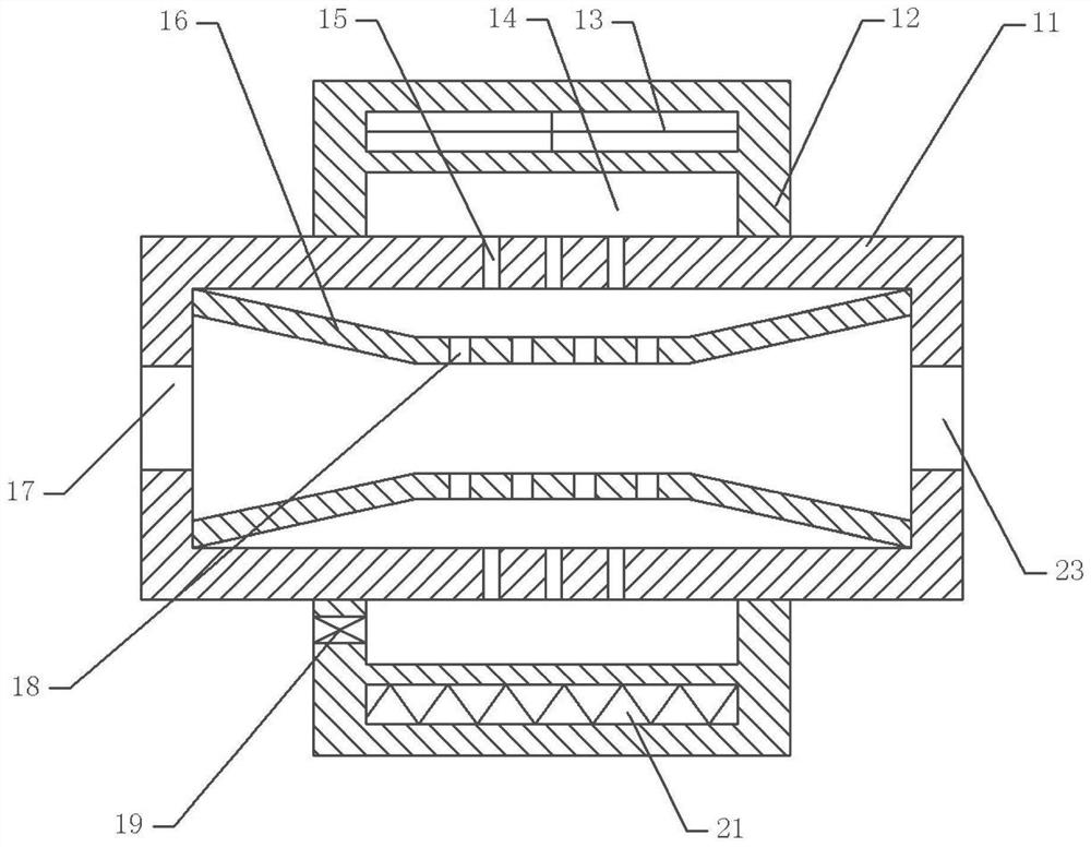
[0037] basically as figure 1 Shown: a fuel cell driven by hydrogen energy, including a humidification system connected to the fuel cell, the humidification system includes a body 11, an air inlet 17 is opened on one side of the body 11, and a second screw is fixed in the air inlet 17 An electromagnetic valve (not shown in the figure), the other side of the body 11 has an air outlet 23, and the second electromagnetic valve 36 (not shown in the figure) is fixed with screws in the air outlet 23, and also includes a controller, the controller It is electrically connected with the first solenoid valve and the second solenoid valve 36 , and the controller is used to control the opening of the first solenoid valve and the second solenoid valve 36 , and then adjust the amount of gas passing through the first solenoid valve and the second solenoid valve 36 .
[0038] The body 11 is covered with a housing box 12, the housing box 12 is fixedly connected with the body 11 with bolts, the h...
Embodiment 2
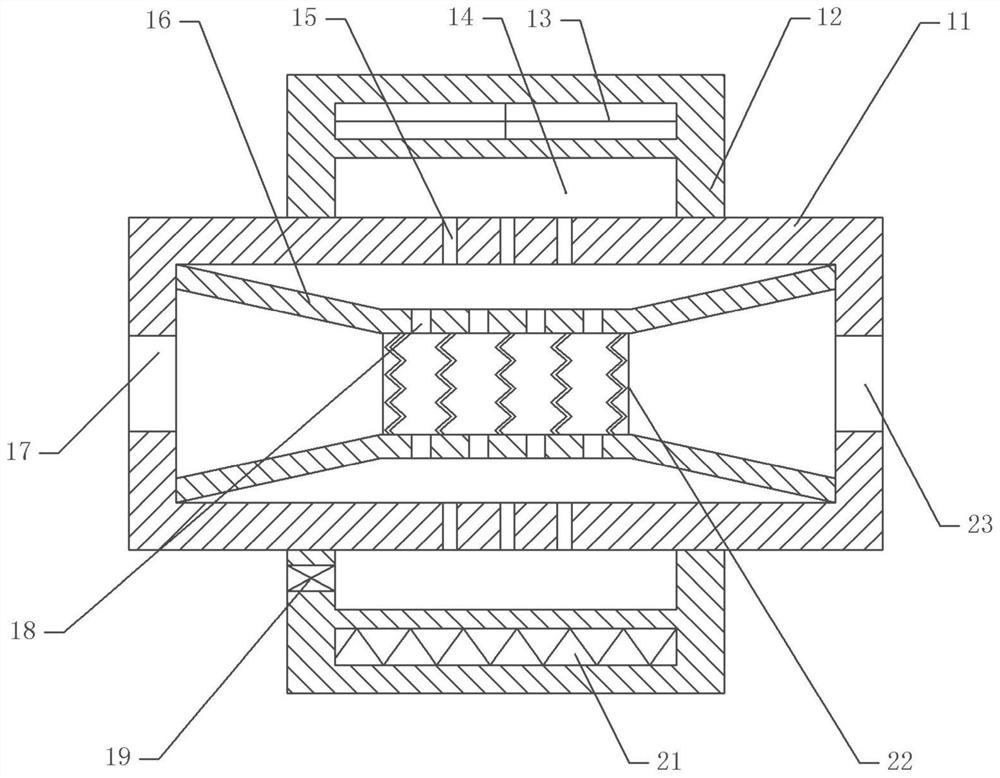
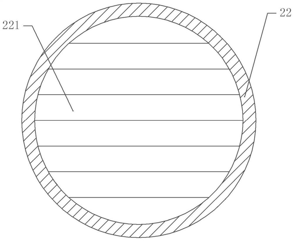
[0045] The difference between embodiment two and embodiment one is that, as attached figure 2 And attached image 3 As shown, both sides of the throat section are fixed with support rings 22 by screws, and a number of fiber membranes 221 uniformly distributed radially along the support ring 22 are arranged between the two support rings 22. In this embodiment, the fiber membranes 221 are wavy. .
[0046] The specific implementation process is as follows:
[0047] After the ultrasonic vibrator 21 atomizes the water, the atomized water can enter the throat section through the air hole 15 and the negative pressure hole 18 and adhere to the fiber membrane 221. When the compressed air flows through the fiber membrane 221, the compressed air is Humidification to improve the humidification effect of compressed air. Since the fiber membrane 221 is wave-shaped, the contact area with the atomized water can be increased, and at the same time, the contact area with the compressed air c...
Embodiment 3
[0049] Basic as attached Figure 4 As shown, a fuel cell fixing structure driven by hydrogen energy is provided, including a main fixing base 31 and a secondary fixing base 32. In this embodiment, the main fixing base 31 is provided with a groove 34, and the containing box 12 can be placed In the groove 34, the two side walls of the groove 34 are rotatably connected with a rotating wheel 25, both sides on the body 11 are provided with a rotating groove 24, the rotating wheel 25 stretches into the rotating groove 24 and the rotating wheel 25 and the rotating The groove 24 is a sliding fit. There is a water inlet on the main fixing seat 31, and the water inlet communicates with the one-way valve 19. In this embodiment, through the cooperation of the rotating wheel 25 and the rotating groove 24, the body 11 is rotated as a whole, and after the body 11 rotates to a certain position, the water inlet and the one-way valve 19 are aligned, so that the water inlet and the one-way valv...
PUM
 Abstract
Description
Claims
Application Information
 - R&D
- Intellectual Property
- Life Sciences
- Materials
- Tech Scout
- Unparalleled Data Quality
- Higher Quality Content
- 60% Fewer Hallucinations
Browse by: Latest US Patents, China's latest patents, Technical Efficacy Thesaurus, Application Domain, Technology Topic, Popular Technical Reports.
© 2025 PatSnap. All rights reserved.Legal|Privacy policy|Modern Slavery Act Transparency Statement|Sitemap|About US| Contact US: help@patsnap.com


