Processing equipment for wave-shaped filter cloth with framework and using method

A processing equipment and wave-shaped technology, which is applied in the field of wave-shaped filter cloth processing equipment, can solve the problems that the solid effect is easily affected by the state of employees, the filter cloth is easily damaged, and the solid efficiency is low, so as to enhance the continuous processing performance and reduce the production cost. , Improve the effect of glue injection automation

Inactive Publication Date: 2021-07-30
昆山卓景电子科技有限公司
View PDF11 Cites 0 Cited by
  • Summary
  • Abstract
  • Description
  • Claims
  • Application Information

AI Technical Summary

Problems solved by technology

[0003] Automobile air conditioner filters usually include filter cloth, which needs to be laminated during use to increase the contact area with the air. The folded filter cloth needs to be solidified to ensure the stacked shape. The efficiency of manual solidification is low, and the solidification effect is easily affected by employees. The state is affected, the solid effect is poor, and the filter cloth is even easily damaged

Method used


Image

  • Processing equipment for wave-shaped filter cloth with framework and using method
  • Processing equipment for wave-shaped filter cloth with framework and using method
  • Processing equipment for wave-shaped filter cloth with framework and using method

Examples


Embodiment Construction

[0034] In order to explain the overall concept of the present invention more clearly, the following will be described in detail by way of examples in conjunction with the accompanying drawings.

[0035] In describing the present invention, it is to be understood that the terms "center", "upper", "lower", "front", "rear", "left", "right", "vertical", "horizontal", The orientation or positional relationship indicated by "top", "bottom", "inner", "outer", "axial", "radial" and "circumferential" are based on the orientation or positional relationship shown in the drawings, only It is for the convenience of describing the present invention and simplifying the description, but does not indicate or imply that the referred device or element must have a specific orientation, be constructed and operated in a specific orientation, and thus should not be construed as limiting the present invention.

[0036] In addition, the terms "first" and "second" are used for descriptive purposes only...


PUM


Abstract

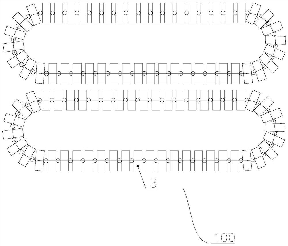
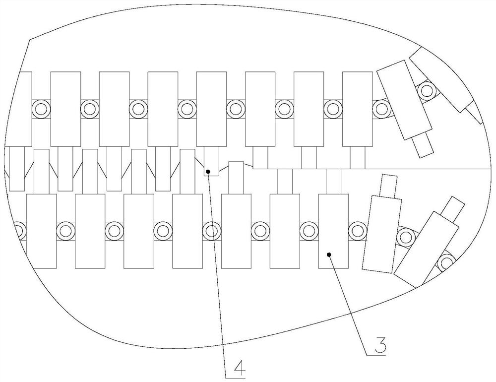
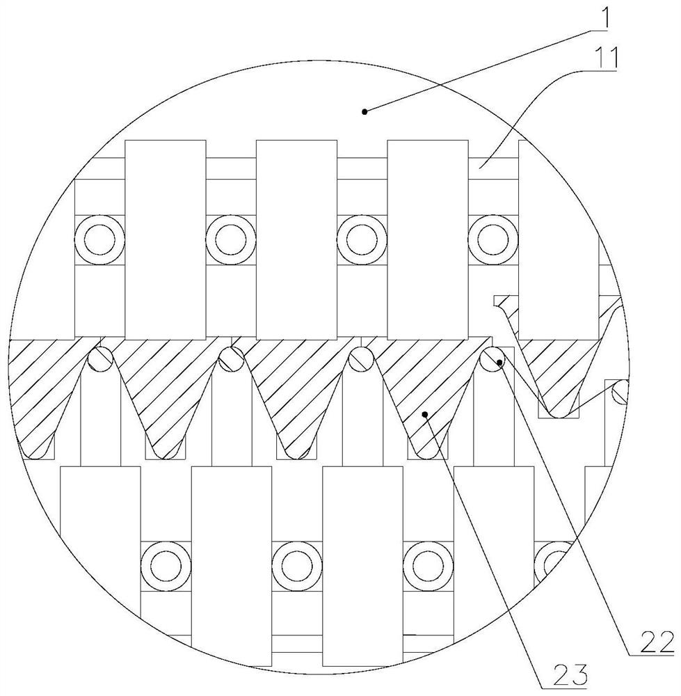
The invention discloses processing equipment for wave-shaped filter cloth with a framework and a using method. The processing equipment for the wave-shaped filter cloth with the framework comprises a rack, shaping rods and move grooves, wherein the shaping rods are arranged on the rack in the direction perpendicular to the length direction of the rack, each shaping rod comprise a lower shaping rod and an upper shaping rod, the lower shaping rods and the upper shaping rods are alternately arranged at equal intervals in the length direction of the rack, and the shaping rods can do translational motion in the direction perpendicular to the axis of the shaping rods and the length direction of the rack; the shaping rods can also do translational motion in the direction parallel to the length direction of the rack; the mold grooves are at least formed in the lower shaping rods or the upper shaping rods and are formed in the sides, which make contact with the wave-shaped filter cloth, of the shaping rods at equal intervals in the length direction of the shaping rods, and glue can be injected into the mold grooves. According to the device, the wave-shaped filter cloth can be shaped into a wavy shape, the shaping efficiency is high, the shaping precision is high, glue can be applied to the surface of the wave-shaped filter cloth and solidified into a framework, the forming effect is improved, the attractiveness is enhanced, and the automation degree is high.

Description

technical field [0001] The invention belongs to the technical field of composite filter cloth processing, and in particular relates to a wave-shaped filter cloth processing equipment with a skeleton and a use method. Background technique [0002] The car air conditioner filter can absorb fine particles (such as dust, dust, etc.) that float in from the outside of the car and are invisible to the naked eye, thereby eliminating the allergic problems (such as tearing, itching, etc.) caused by fine particles of car drivers and passengers. It can also prevent fine particles from mold and multiply bacteria in the air conditioning system (HVAC system), prevent the car from emitting peculiar smell when the air conditioning system is heated or cooled, and remove unpleasant odors and gas oil smells. The composite filter can also filter the exhaust gas emitted by automobiles and tractors, thereby cutting off the source of foreign odors entering the interior of the automobile and ensurin...

Claims


Application Information

Patent Timeline
Patent Type & Authority Applications(China)
IPC IPC(8): B01D39/08B01D46/52B60H3/06
CPCB01D39/08B01D46/521B60H3/06B01D2239/10
Inventor 叶得贤
Owner 昆山卓景电子科技有限公司
Why Eureka
Try Eureka