
Mechanical and electrical integrated injection molding device for workpiece production and processing

An electromechanical and integrated technology, which is applied in the field of electromechanical integrated injection molding devices for workpiece production and processing, can solve problems such as uneven molding materials, air bubbles, and uncertain movement cycles of piston rods.

Active Publication Date: 2021-07-30
CHONGQING CITY MANAGEMENT COLLEGE
View PDF5 Cites 1 Cited by
  • Summary
  • Abstract
  • Description
  • Claims
  • Application Information

AI Technical Summary

Problems solved by technology

In the injection molding process, the moving stroke and moving speed of the piston rod are generally controlled by using the control valve to control the opening of the oil circuit connected to the pressure accumulator, because the oil pressure increases and decreases gradually , in the prior art, the method of controlling the piston rod by controlling the oil pressure has low control precision and slow corresponding speed, which makes the movement cycle of the piston rod relatively uncertain, which leads to uneven molding materials injected into the mold, and easily causes air bubbles in the product and other defects, and, in the mold with multiple injection holes, the accuracy of the injection cycle and injection volume of the molding material is required to be higher

Method used


Image

  • Mechanical and electrical integrated injection molding device for workpiece production and processing
  • Mechanical and electrical integrated injection molding device for workpiece production and processing
  • Mechanical and electrical integrated injection molding device for workpiece production and processing

Examples


Embodiment Construction

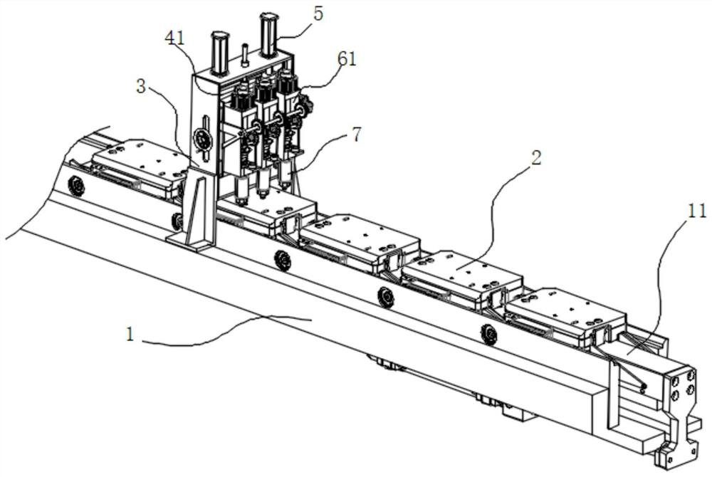
[0041] see figure 1 , in an embodiment of the present invention, an electromechanical integrated injection molding device for workpiece production and processing, including a conveying tank 1, a plurality of molds 2 are evenly placed in the conveying tank 1, and a step-by-step conveying mold 2 is provided at the bottom of the conveying tank 1 The advancing slide bar 11, the gantry 3 is fixed on the conveying trough 1;

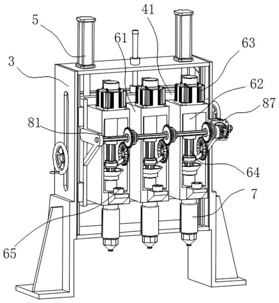
[0042] The gantry 3 is provided with an elevating platform 41 that can slide up and down, and a plurality of connecting seats 61 are slidably distributed in the elevating platform 41 along the direction perpendicular to the advancing direction of the conveying trough 1, and each connecting seat 61 is provided with Injection molded components7.

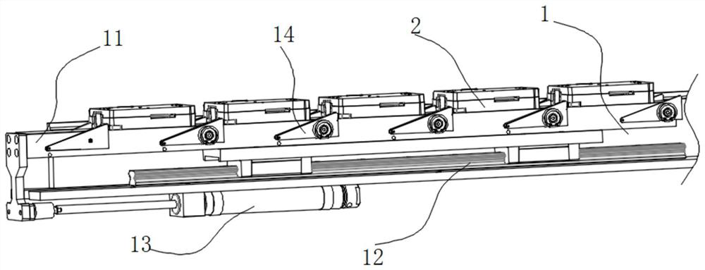
[0043] see figure 2 , in this embodiment, the bottom of the delivery tank 1 is fixed with a guide rail 12, and the guide rail 12 is slidably provided with a pusher slide bar 11, the width of the push slide bar 11 is ...


PUM


Abstract

The invention discloses a mechanical and electrical integrated injection molding device for workpiece production and machining, which comprises a conveying groove, wherein a plurality of molds are evenly placed in the conveying groove, a pushing sliding rod capable of conveying the molds in a stepping mode is arranged at the bottom of the conveying groove, and a portal frame is fixed to the conveying groove; a lifting table is arranged in the portal frame in an up-down sliding mode, a plurality of connecting bases are distributed in the lifting table in a sliding mode in the direction perpendicular to the advancing direction of the conveying groove, and an injection molding assembly is arranged in each connecting base; an injection molding motor is fixed above the connecting base, and an output shaft of the injection molding motor is connected with a hollow rotating shaft; and a spline piston rod is connected below the hollow rotating shaft in a torque transmission manner. Compared with the prior art, the mechanical and electrical integrated injection molding device has the advantages that a piston connecting rod is connected to the different positions of the sliding groove gear, the initial position and stroke of each spline piston rod can be adjusted, and the spline piston rods can operate according to the preset period so as to be suitable for the injection amount and injection time of plastic liquid of the molds.

Description

technical field [0001] The invention relates to the technical field of injection molding devices, in particular to an electromechanical integrated injection molding device for workpiece production and processing. Background technique [0002] The injection molding device uses the injection cylinder to advance the injection plunger in the sleeve, and presses the molding material (such as molten plastic liquid) in the sleeve to the cavity formed between the molds, thereby injecting and filling the molding material to the cavity. [0003] In the injection process of the injection molding device, the working oil accumulated in the accumulator is usually supplied to the injection cylinder to push the piston rod, so that the injection plunger is repeatedly moved to periodically inject the molding material into the mold. In the injection molding process, the moving stroke and moving speed of the piston rod are generally controlled by using the control valve to control the opening ...

Claims


Application Information

Patent Timeline
IPC IPC(8): B29C45/04B29C45/13B29C45/54
CPCB29C45/0408B29C45/13B29C45/54Y02P70/10
Inventor 谢祥洲任琪梁涛
Owner CHONGQING CITY MANAGEMENT COLLEGE
Learn More