
New energy automobile battery damping device

A technology of new energy vehicles and shock absorbing devices, which is applied in the direction of battery/fuel cell control devices, electric power devices, electric vehicles, etc. It can solve the problems of continuous collision of batteries, affecting the service life of batteries, and poor heat dissipation, so as to accelerate the heat dissipation. Dispersion, increase the ventilation effect, avoid the effect of higher temperature

Active Publication Date: 2021-07-30
HENAN POLYTECHNIC
View PDF8 Cites 9 Cited by
  • Summary
  • Abstract
  • Description
  • Claims
  • Application Information

AI Technical Summary

Problems solved by technology

[0003] The current new energy vehicle batteries install the battery box inside the car through bolts and other fixed parts. When driving on a bumpy road, the battery in the battery box will vibrate continuously, which will change the structure distribution inside the battery, and it will easily lead to continuous collisions between multiple batteries, which will affect the service life of the battery, and in the battery box When working, a large amount of heat will be emitted in the battery box. At present, only the heat conduction of the battery box itself is used to dissipate heat, resulting in poor heat dissipation. In high temperature weather, it is easy to cause the battery to spontaneously ignite.

Method used


Image

  • New energy automobile battery damping device
  • New energy automobile battery damping device
  • New energy automobile battery damping device

Examples


Embodiment Construction

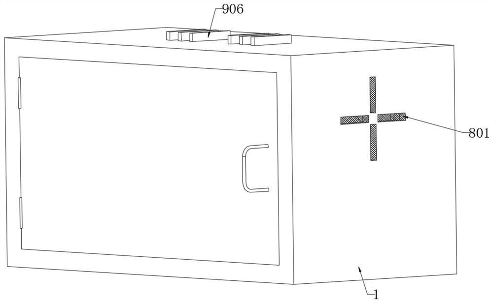
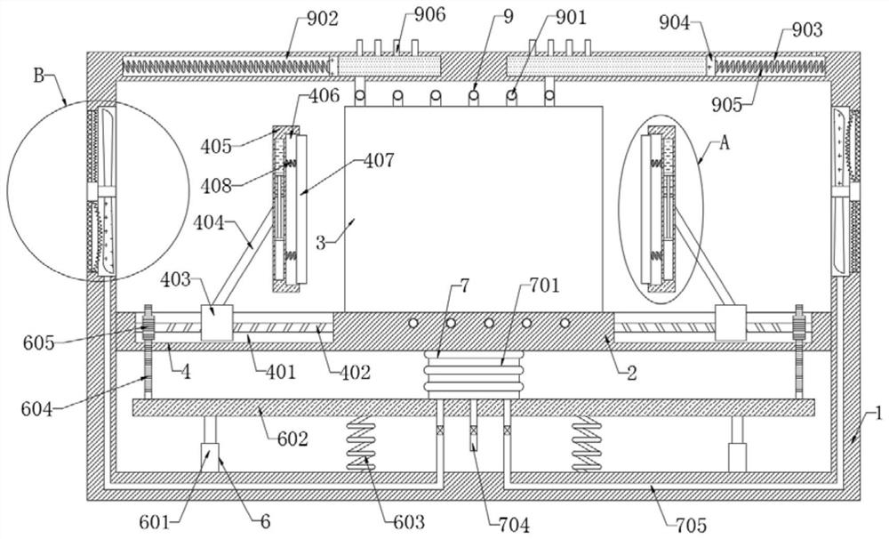
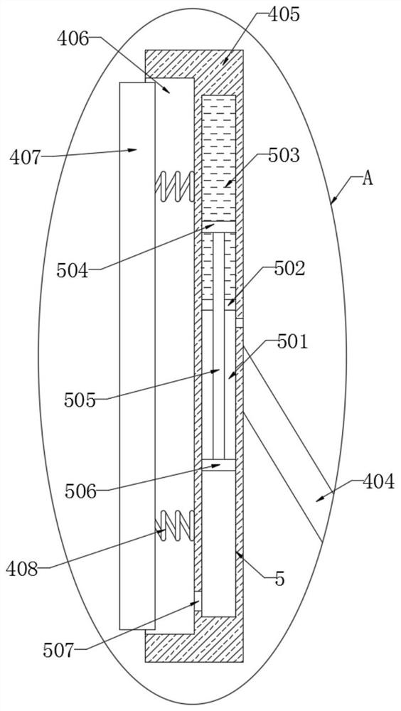
[0026] refer to Figure 1-5 , a new energy vehicle battery shock absorber, comprising a shell 1, the inner wall of the shell 1 is fixedly connected with a fixed plate 2, the upper end of the fixed plate 2 is fixedly connected with a battery box 3, and the fixed plate 2 is provided with a clamp for the battery box 3 Tight clamping mechanism 4, clamping mechanism 4 comprises two chutes 401 provided with the side walls of fixing plate 2, the inner wall of chute 401 is connected with screw 402 for rotation, and the side wall of lead screw 402 is threadedly connected with slider 403. The side wall of the block 403 is slidingly connected with the inner wall of the chute 401, and the upper end of the slider 403 is fixedly connected with a vertical plate 405 through an oblique bar 404. The side wall of the vertical plate 405 is provided with a groove 406, and the inner wall of the groove 406 is sealed and slidably connected with a splint 407. The side wall of 407 is elastically connec...


PUM


Abstract

The invention discloses a new energy automobile battery damping device, and the damping device comprises a shell, a fixed plate is fixedly connected to the inner wall of the shell, a battery box is fixedly connected to the upper end of the fixed plate, a clamping mechanism for clamping the battery box is arranged on the fixed plate, and the clamping mechanism comprises two sliding grooves formed in the side walls of the fixed plate. The inner wall of each sliding groove is rotationally connected with a lead screw, and the side wall of the lead screw is in threaded connection with a sliding block. By arranging the transmission mechanism and the clamping mechanism, the battery box can be protected at the first time when the shell vibrates, vibration on the shell is effectively utilized, the situation that the service life of a battery is affected due to continuous vibration of the battery in the battery box is avoided, and by arranging a damping mechanism, when the battery box is subjected to large vibration, under the action of the non-Newtonian liquid, the clamping plates can be inhibited from sliding, so that the clamping plates can quickly and stably clamp the battery box, and the stability of the battery box is accelerated.

Description

technical field [0001] The invention relates to the technical field of new energy vehicles, in particular to a battery damping device for new energy vehicles. Background technique [0002] New energy vehicles are a new generation of vehicles produced in recent years to reduce oil energy loss and reduce air pollution. They are mainly powered by the discharge of their internal lithium battery packs. [0003] The current new energy vehicle batteries install the battery box inside the car through bolts and other fixed parts. When driving on a bumpy road, the battery in the battery box will vibrate continuously, which will change the structure distribution inside the battery, and it will easily lead to continuous collisions between multiple batteries, which will affect the service life of the battery, and in the battery box When working, a large amount of heat will be emitted in the battery box. At present, only the heat conduction of the battery box itself is used to dissipate ...

Claims


Application Information

Patent Timeline
Patent Type & Authority Applications(China)
IPC IPC(8): B60K1/04B60L50/64B60L58/26B01D46/10H01M50/242H01M50/244H01M50/249H01M10/613H01M10/625H01M10/6568H01M10/6563
CPCB60K1/04B60L50/64B60L58/26B01D46/10H01M10/613H01M10/625H01M10/6568H01M10/6563Y02T10/70
Inventor 王悬悬陈海燕王彪王正刘明库陈国强
Owner HENAN POLYTECHNIC
Learn More