Embroidery machine driver

A driver and embroidery machine technology, which is applied in the field of embroidery machine drivers and embroidery machines, can solve problems such as troublesome and difficult adjustment of driving stroke, and achieve the effects of simple adjustment, avoiding scale misreading, and easy inspection

Active Publication Date: 2021-07-30
绍兴晶远创意设计有限公司
View PDF9 Cites 1 Cited by
  • Summary
  • Abstract
  • Description
  • Claims
  • Application Information

AI Technical Summary

Problems solved by technology

[0002] The driving stroke of the existing embroidery machine is difficult to adjust
Therefore, in order to ensure the smooth progress of embroidery, when the embroidery machine is parked, the height of the bottom of the presser foot from the needle plate, the height of the shuttle box and the length of the needle bar need to be adjusted according to the thickness of the embroidered fabric. very troublesome

Method used


Image

  • Embroidery machine driver
  • Embroidery machine driver
  • Embroidery machine driver

Examples


Embodiment Construction

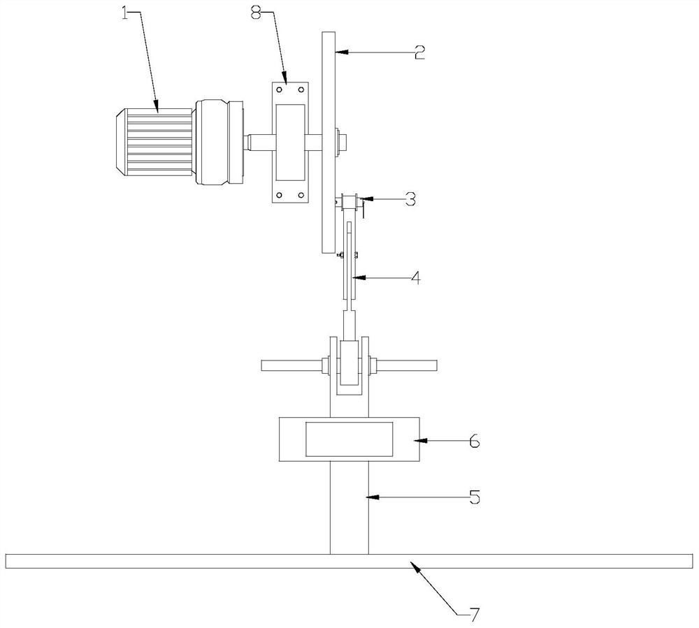
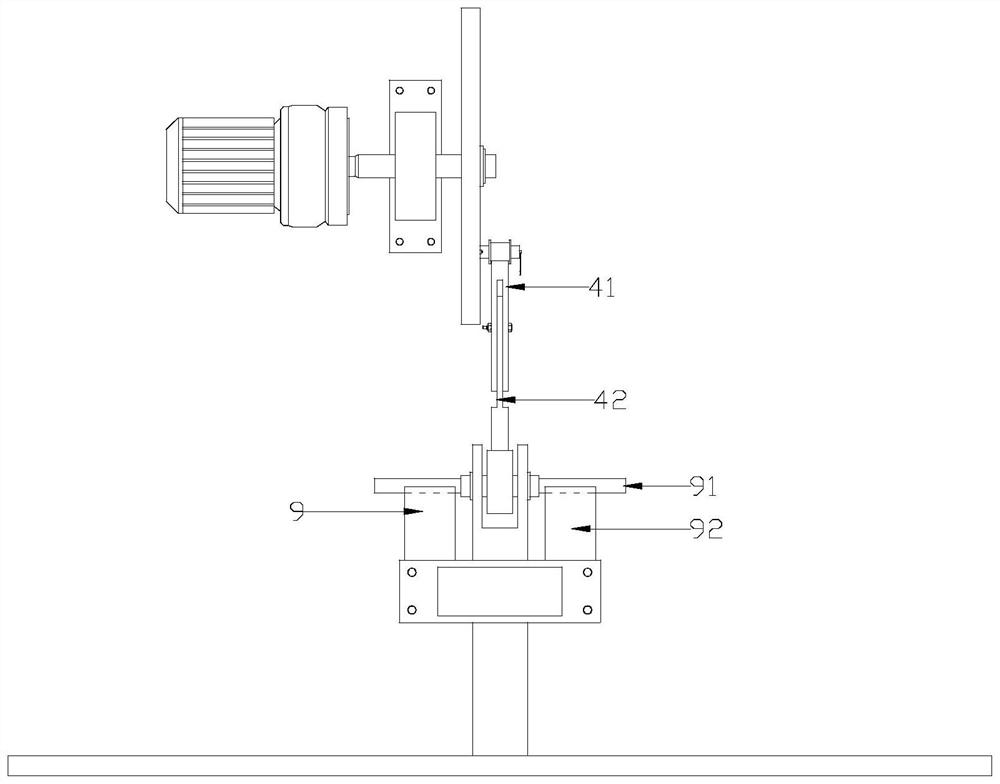
[0022] refer to Figure 1 to Figure 5 , an embroidery machine driver of the present invention, comprising a motor 1, a runner 2, a handle 3, a rocker 4, a slide bar 5, a guide sleeve 6 and an end plate 7, one side of the runner 2 is concentrically fixed on the motor 1 The end of the output shaft, the rotating handle 3 is eccentrically and detachably installed on the other side of the rotating wheel 2, one end of the rocker 4 is sleeved outside the rotating handle 3 and the other end is hinged with one end of the sliding rod 5 , the other end of the slide bar 5 is connected to the end plate 7 after passing through the guide sleeve 6, and the motor 1 and the guide sleeve 6 are respectively fixed on the embroidery machine.

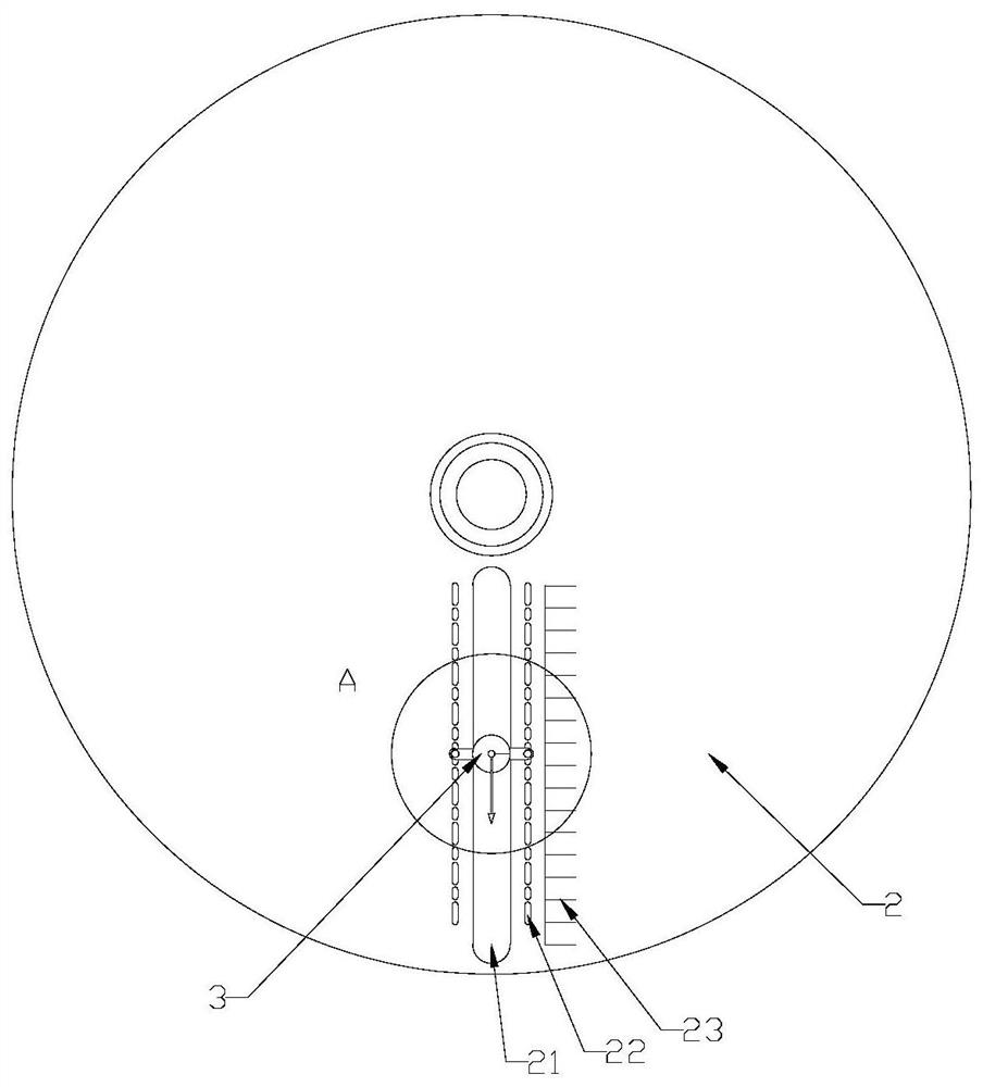
[0023] The side of the runner 2 away from the motor 1 is provided with a chute 21, the rotating handle 3 is slidably connected in the chute 21 and can approach or move away from the center of rotation of the runner 2 along the chute 21, the runner 2 2 The si...


PUM


Abstract

The invention discloses an embroidery machine driver. The embroidery machine driver comprises a motor, a rotating wheel, a rotating handle, a rocker, a sliding rod, a guide sleeve and an end plate; one side of the rotating wheel is concentrically fixed to the end of an output shaft of the motor; the rotating handle is eccentrically and detachably installed on the other side of the rotating wheel; one end of the rocker is arranged outside the rotating handle in a sleeving mode, and the other end of the rocker is hinged to one end of the sliding rod; the other end of the sliding rod is connected with the end plate after penetrating through the guide sleeve; and the motor and the guide sleeve are fixed on an embroidery machine. According to the invention, the motor drives the rotating wheel and the rotating handle to rotate, the rocker drives the sliding rod to move up and down along the guide sleeve, and therefore the end plate and multiple needle rods installed on the end plate are driven to move up and down; and during shutdown, the eccentrically-arranged rotating handle can move along a sliding groove and is fixed, and the distance between the rotating handle and the rotating center of the rotating wheel is adjusted, so that the stroke of the needle rods is changed, and the adjustment is simple and convenient.

Description

【Technical field】 [0001] The invention relates to the technical field of embroidery machines, in particular to the technical field of embroidery machine drivers. 【Background technique】 [0002] The driving stroke of the existing embroidery machine is difficult to adjust. Therefore, in order to ensure the smooth progress of embroidery, when the embroidery machine is parked, the height of the bottom of the presser foot from the needle plate, the height of the shuttle box and the length of the needle bar need to be adjusted according to the thickness of the embroidered fabric. Very troublesome. 【Content of invention】 [0003] The purpose of the present invention is to solve the problems in the prior art, and propose an embroidery machine driver, which can simply and conveniently adjust the movement stroke of the needle bar. [0004] To achieve the above object, the present invention proposes an embroidery machine driver, comprising a motor, a runner, a handle, a rocker, a s...

Claims


Application Information

Patent Timeline
Patent Type & Authority Applications(China)
IPC IPC(8): D05C11/06
CPCD05C11/06
Inventor 俞志远高晶
Owner 绍兴晶远创意设计有限公司
Why Eureka
Try Eureka