Eureka AIR delivers breakthrough ideas for toughest innovation challenges, trusted by R&D personnel around the world.

Offshore wind power single-pile foundation scouring protection device

A monopile foundation and offshore wind power technology, applied in protection devices, infrastructure engineering, construction, etc., can solve problems such as low construction efficiency, difficulty in slowing down seawater flow, and difficulty in accurately laying to the design position

Active Publication Date: 2021-07-30
HUANENG CLEAN ENERGY RES INST +2
View PDF10 Cites 17 Cited by
  • Summary
  • Abstract
  • Description
  • Claims
  • Application Information

AI Technical Summary

Problems solved by technology

The connection between sandbags or between stones is usually very weak, and it is difficult to form a complete whole. When the current velocity is large, it is easy to be washed away, and it is difficult to play a protective role
In addition, sandbags or riprap only serve to reinforce the surface soil, and it is difficult to slow down the seawater flow rate and reduce the generation of large vortices before and after the single pile.
At the same time, the sandbags around the pile or the riprap around the pile still have problems such as low construction efficiency and difficulty in accurately laying them to the designed position during the construction process.

Method used


Image

  • Offshore wind power single-pile foundation scouring protection device
  • Offshore wind power single-pile foundation scouring protection device
  • Offshore wind power single-pile foundation scouring protection device

Examples


Embodiment Construction

[0036] The present invention is described in further detail below in conjunction with accompanying drawing:

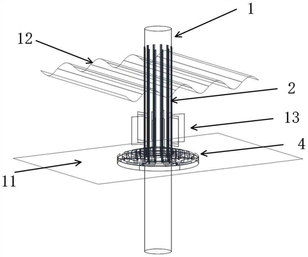
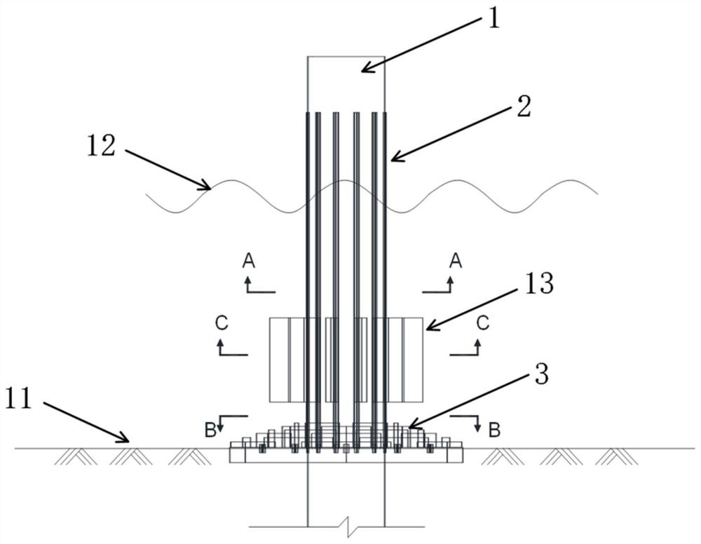
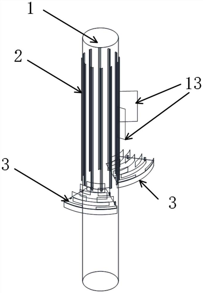
[0037] Such as figure 1 As shown, an offshore wind power single-pile foundation scour protection device includes a single-pile foundation 1, a spoiler bottom plate 3 and a lateral spoiler 13; one end of the single-pile foundation 1 is fixed in the seabed, and the spoiler bottom plate 3 is fixed on the single pile On the outside of the foundation 1, a plurality of annular spoilers 5 are fixed on the upper end of the spoiler bottom plate 3, and the lower end of the spoiler bottom plate 3 is in contact with the seabed surface.

[0038] Such as figure 2 , Figure 4 As shown, the single pile foundation 1 is a column structure, which is composed of steel pipes with equal outer diameters; image 3 As shown, the spoiler bottom plate 3 adopts a fan-shaped structure, and there are a plurality of fixed chute 2 in a circumferential array on the outer side of the monopile found...


PUM


Abstract

The invention discloses an offshore wind power single-pile foundation scouring protection device. The offshore wind power single-pile foundation scouring protection device is characterized in that a turbulent flow bottom plate and lateral turbulent flow plates are fixed on a single-pile foundation; one end of the single-pile foundation is fixed in a seabed, the single-pile foundation is firmly connected with the seabed and is not easily scoured away by ocean current, and the turbulent flow bottom plate is fixed on the outer side of the single-pile foundation to form a seabed protection layer structure; multiple annular turbulent flow plates are fixed to the upper end of the turbulent flow bottom plate, and the annular turbulent flow plates can effectively reduce the water flow velocity at the seabed surface and reduce the seabed scouring effect; meanwhile, the pressure of seawater on the turbulent flow bottom plate can be utilized, and the scouring phenomenon between the single-pile foundation and the seabed is effectively prevented; the lower end of the turbulent flow bottom plate makes contact with the surface of the seabed; meanwhile, the bottom of the turbulent flow bottom plate can fix the bottom of the seabed; the plurality of lateral turbulent flow plates are evenly arrayed in the circumferential direction of the single-pile foundation, the purpose of weakening vortex formation around a pile body through the lateral turbulent flow plates is achieved, and then the seabed scouring effect is weakened; and the structure is simple, the flow speed of seawater around the pile is effectively reduced, and generation of large vortexes around the pile is reduced.

Description

technical field [0001] The invention belongs to the technical field of offshore wind power generation, and in particular relates to an erosion protection device for single pile foundations of offshore wind power. Background technique [0002] In the field of offshore wind power, large-diameter monopile foundation is a common form of foundation structure. The single pile foundation needs to bear various natural environmental loads such as wind, waves, and currents during its use. Due to its unique circular cross-section, after the ocean current passes through the single pile, it is easy to form various vortex structures such as "horseshoe vortex" in the front and back of the pile body. Local scour, which poses a great threat to the security and stability of the infrastructure. Designing and arranging foundation scour protection measures, controlling and reducing soil scour around piles, and weakening the formation of horseshoe nests are issues that must be considered in the...

Claims


Application Information

Patent Timeline
Patent Type & Authority Applications(China)
IPC IPC(8): E02D31/00E02D31/06E02D15/08E02D27/42E02D27/44E02D27/12
CPCE02D31/00E02D31/06E02D15/08E02D27/42E02D27/425E02D27/44E02D27/12Y02E10/727
Inventor 邱旭穆延非张波牛晨晖桂洪波杭兆峰张宇彭泳江
Owner HUANENG CLEAN ENERGY RES INST
Why Eureka
Eureka Blog
Learn More