Portable supporting device for building construction

A technology for supporting devices and building construction, which is applied in construction, building structure, and processing of building materials, etc., can solve problems such as increasing the difficulty of operation by construction personnel, increasing the working strength of construction personnel, and inability to adjust the height of supporting devices.

Inactive Publication Date: 2021-07-30
丁奥林
View PDF0 Cites 0 Cited by
  • Summary
  • Abstract
  • Description
  • Claims
  • Application Information

AI Technical Summary

Problems solved by technology

[0003] In the process of building construction, construction personnel often install equipment or perform some construction operations while standing for a long time. Usually, they also encounter situations where they need to squat or the installation position is relatively low. In this case, construction personnel need to move Construction by bending the legs or kneeling on the ground not only increases the difficulty of the construction personnel's operation, but also greatly consumes the physical strength of the construction personnel, and the existing construction support device is cumbersome to operate, which cannot make the construction personnel more relaxed and comfortable. Quickly adjust the height of the support device, which increases the work intensity of the construction personnel

Method used


Image

  • Portable supporting device for building construction
  • Portable supporting device for building construction
  • Portable supporting device for building construction

Examples


Embodiment 1

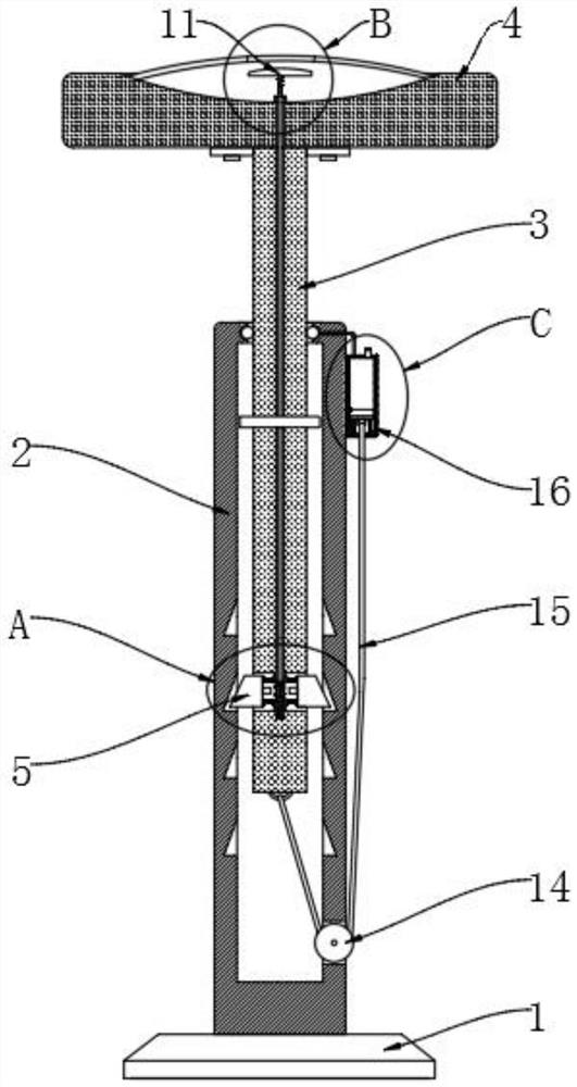
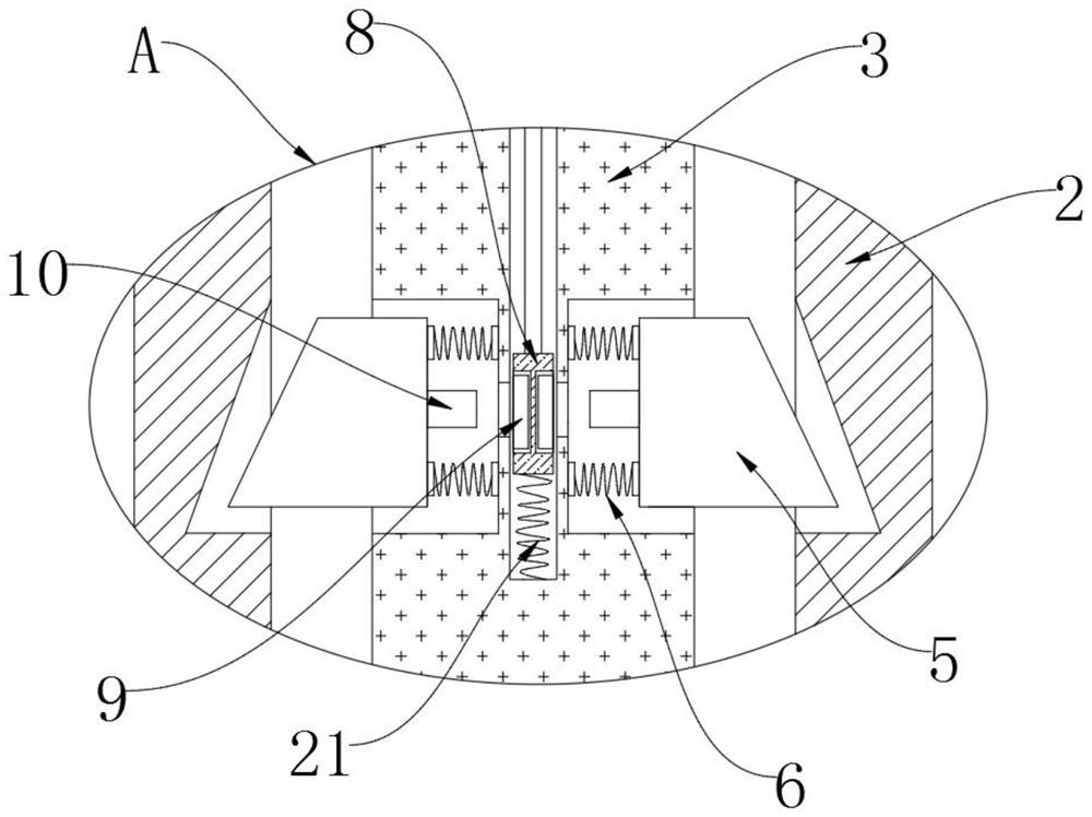
[0024] refer to figure 1 , 3 , 4, including a support base 1 and a support cylinder 2 fixedly installed on the upper surface of the support base 1, the inner wall of the support cylinder 2 is slidably connected with a movable support column 3, the top of the movable support column 3 is fixedly installed with a cushion 4, and the movable support column 3 The surface of the surface is provided with a mounting groove, and the inner wall of the mounting groove is slidably connected with a trapezoidal clamping block 5, and a first compression spring 6 is fixedly installed between the side of the trapezoidal clamping block 5 and the inner wall of the mounting groove, and the support tube 2 The inner wall is provided with a clamping groove compatible with the trapezoidal clamping block 5, and the inside of the movable support column 3 is provided with a vertical strip groove, and the inner wall of the vertical strip groove is provided with an operating connecting rod 7, and the botto...

Embodiment 2

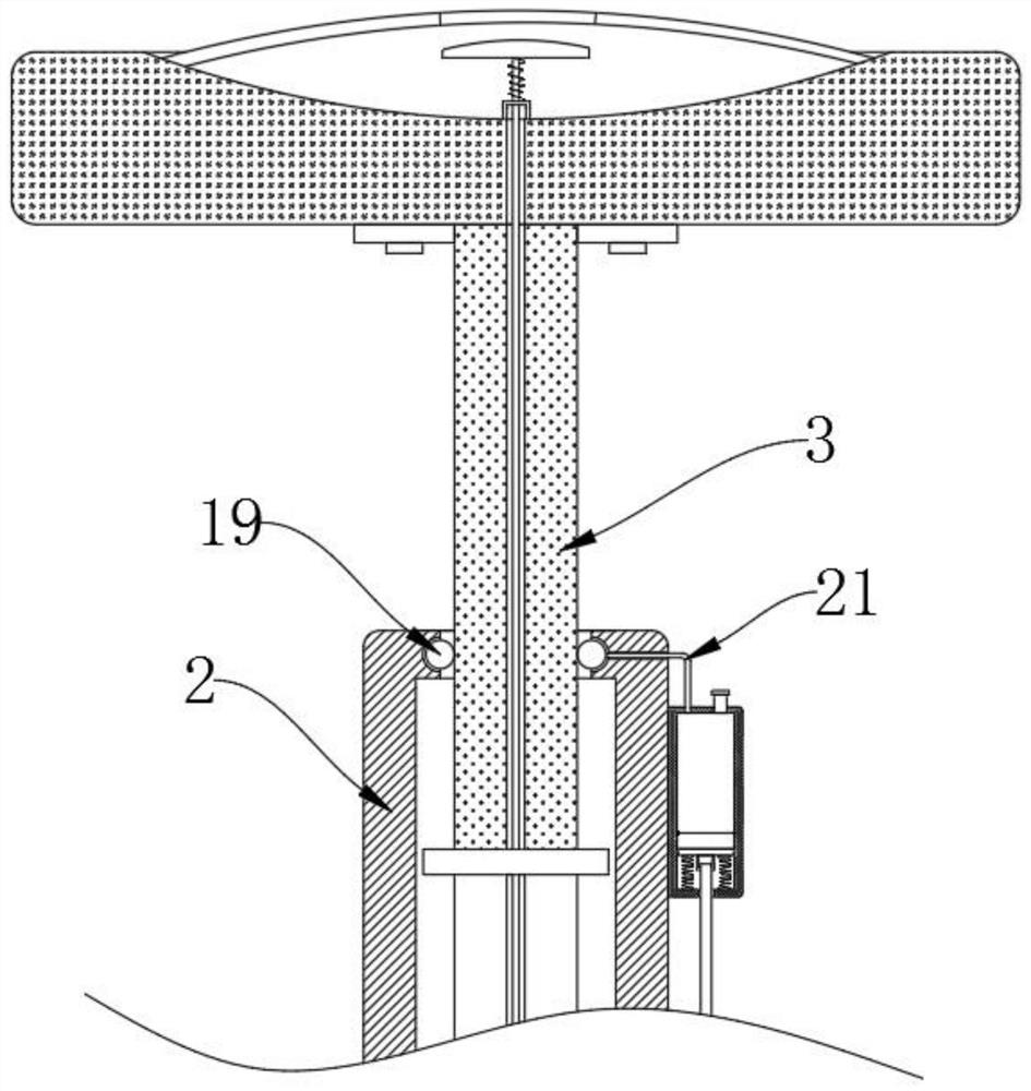
[0028] refer to figure 2 and Figure 5 , different from Embodiment 1, the surface of the support tube 2 is provided with a pulley hole, the inner wall of the pulley hole is connected to the pulley 14 through the rotation of the shaft, the surface of the pulley 14 is wound with a stay cord 15, and one end of the stay cord 15 extends to the support tube 2, and is fixedly connected with the bottom of the movable support column 3.

[0029] The surface of the support cylinder 2 is fixedly equipped with a piston cylinder 16, the inner wall of the piston cylinder 16 is slidably connected with a piston head 17, and a fourth compression spring 18 is arranged between the lower surface of the piston head 17 and the inner wall of the piston cylinder 16, and the piston head 17 The lower surface is fixedly connected with the other end of stay cord 15.

[0030] The bottom opening of the support cylinder 2 is provided with a ball 19, the surface of the ball 19 is slidingly connected with t...


PUM


Abstract

The invention discloses a portable supporting device for building construction. The portable supporting device comprises a supporting base and a supporting cylinder fixedly installed on the upper surface of the supporting base, a movable supporting column is slidably connected to the inner wall of the supporting cylinder, a cushion is fixedly installed at the top end of the movable supporting column, and an installation groove is formed in the surface of the movable supporting column. According to the portable supporting device for building construction, by arranging the movable supporting column, a trapezoidal clamping block and a clamping groove, when a constructor needs to adjust the height of the supporting device, the constructor only needs to drive the cushion upwards, the cushion drives the movable supporting column to move upwards, the trapezoidal clamping block slides out of the clamping groove, then the trapezoidal clamping block is attracted through a magnetic block, so that the trapezoidal clamping block cannot move, after the height is adjusted, the trapezoidal clamping block and the magnetic block can be separated only by pressing a pressing plate on the cushion, then the trapezoidal clamping block is restored to the use state, and the effect of conveniently adjusting the height of the device is achieved.

Description

technical field [0001] The invention relates to the technical field of building construction, in particular to a portable supporting device for building construction. Background technique [0002] Building construction refers to the production activities in the implementation stage of engineering construction. It is the construction process of various buildings. It can also be said to be the process of turning various lines on the design drawings into physical objects at designated locations. It includes basic engineering construction. , main structure construction, roofing engineering construction, decoration engineering construction, etc., the place where the construction work is called "building construction site" or "construction site", also called construction site. [0003] In the process of building construction, construction personnel often install equipment or perform some construction operations while standing for a long time. Usually, they also encounter situation...

Claims


Application Information

Patent Timeline
Patent Type & Authority Applications(China)
IPC IPC(8): E04G21/00A47C9/00A47C3/24
CPCA47C3/24A47C9/00E04G21/00
Inventor 丁奥林
Owner 丁奥林
Why Eureka
Try Eureka