Breathing cavity type lubricating moisture-proof device and using method thereof

A breathing chamber and breathing joint technology, used in lubricating parts, engine lubrication, variable displacement pump components, etc., can solve problems such as emulsification, short continuous running time, compression damage, etc.

Inactive Publication Date: 2021-07-30
NANJING VOCATIONAL UNIV OF IND TECH
View PDF6 Cites 0 Cited by
  • Summary
  • Abstract
  • Description
  • Claims
  • Application Information

AI Technical Summary

Problems solved by technology

When the compressor stops working, especially during plateau or cold nights, the temperature in the compressor body drops greatly, and the water vapor contained in the air that originally entered and remained in the compressor cavity will condense into larger water droplets and die. Dispersed and mixed into the lubricating oil in the body, over time it will cause emulsification of the lubricating oil and reduce the lubricating effect of the lubricating oil, which will cause increased friction and heat generation of the parts and lead to carbonization of the lubricating oil at high temperature, resulting in lubrication failure and failure. Lead to the reduction of the operating efficiency and service life of the compressor, and even the rapid damage of the compression
Especially for the scraper compressor used in vehicles, since its operating condition is mainly intermittent operation, and the continuous operation time is very short each time, the temperature of the lubricating oil is usually not raised enough to allow the lubricating oil to The water vapor in the oil evaporates as much as possible, so the emulsification problem of the lubricating oil often leads to serious consequences

Method used


Image

  • Breathing cavity type lubricating moisture-proof device and using method thereof
  • Breathing cavity type lubricating moisture-proof device and using method thereof
  • Breathing cavity type lubricating moisture-proof device and using method thereof

Examples


Embodiment Construction

[0018] In order to make the technical means, creative features, goals and effects achieved by the present invention easy to understand, the present invention will be further described below in conjunction with specific embodiments.

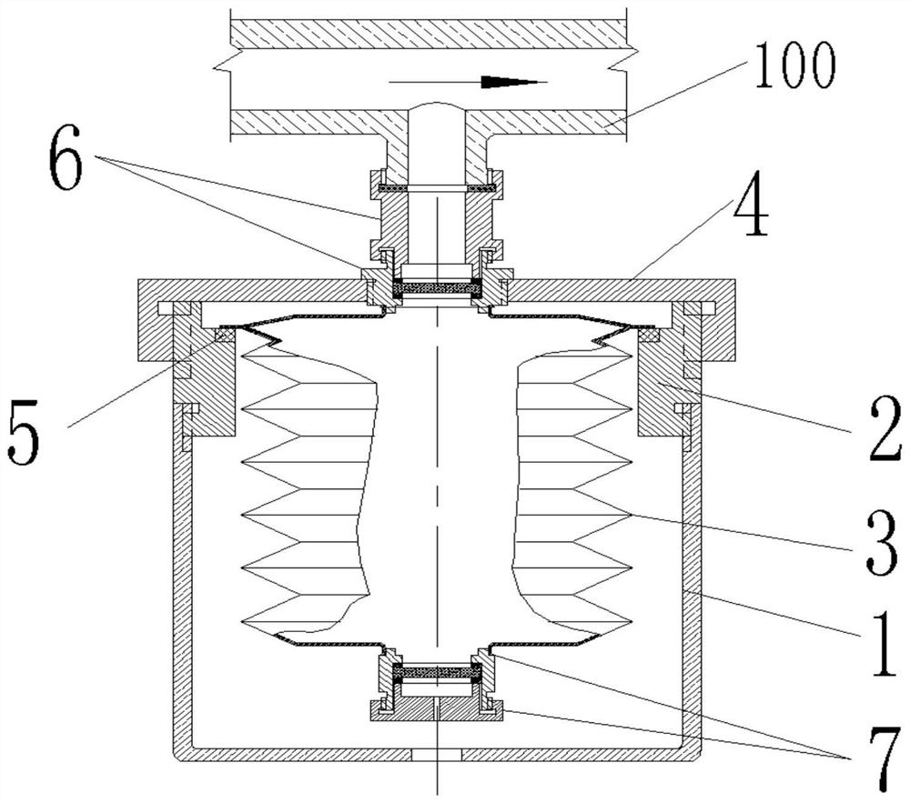
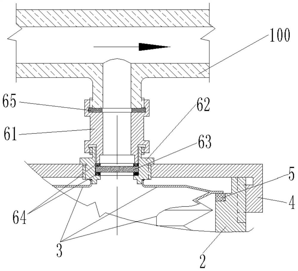
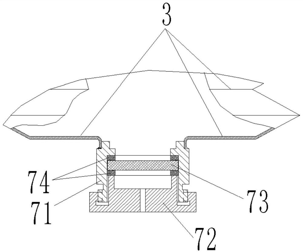
[0019] Embodiments of the present invention refer to Figure 1-3 , a breathing cavity type lubricating moisture-proof device, comprising a cup 1, a cup hoop 2 threadedly connected to the upper end of the cup 1, a corrugated cavity 3 arranged inside the cup 1, a cup cover 4 threadedly connected to the upper end of the cup hoop 2, The breathing mouth 6 and the emptying mouth 7, the breathing mouth 6 is screwed to the upper side of the cup cover 4, the upper end of the corrugated cavity 3 is welded to the lower end of the breathing mouth 6, and the upper flange of the corrugated cavity 3 is supported on the cup by the pressure equalizing pad 5 The upper end of the hoop 2 and the emptying nozzle 7 are welded to the lower end of the bellows chamber 3 ,...


PUM


Abstract

The invention discloses a breathing cavity type lubricating moisture-proof device and a using method thereof, and relates to the field of general machinery. The breathing cavity type lubricating moisture-proof device comprises a cup hood, a cup hoop in threaded connection to the upper end of the cup hood, a corrugated cavity formed in the inner side of the cup hood, a cup cover in threaded connection to the upper end of the cup hoop, a breathing nozzle and an emptying nozzle. The breathing nozzle is in threaded connection to the upper side of the cup cover, the upper end of the corrugated cavity is connected to the lower end of the breathing nozzle in a sleeved manner through welding, a flange at the upper part of the corrugated cavity is supported at the upper end of the cup hoop through a pressure equalizing pad, the emptying nozzle is connected to the lower end of the corrugated cavity in a sleeved manner through welding, and a breathing sieve in the breathing nozzle and an exhaust sieve in the emptying nozzle are made of molecular sieves. A telescopic semi-closed metal foil breathing cavity and a molecular sieve filter are used for achieving interaction between redundant water vapor in a compressor cavity and the external environment, generation of supersaturated water vapor in the compressor cavity is avoided, and therefore emulsification of lubricating oil is avoided so as to guarantee reliable lubrication and safe and efficient running of a compressor.

Description

technical field [0001] The invention relates to the field of general machinery, in particular to a breathing cavity type lubricating and moisture-proof device and a using method thereof. Background technique [0002] As a general-purpose machine, compressors are widely used. In most cases, the safe and efficient operation of compressors is inseparable from lubricating oil to ensure the lubrication and cooling of parts inside the compressor. However, when the compressor is running, gas, especially air Inevitably contains water vapor, especially in high temperature and humid environment, the air entering the compressor contains more moisture. When the compressor stops working, especially during plateau or cold nights, the temperature in the compressor body drops greatly, and the water vapor contained in the air that originally entered and remained in the compressor cavity will condense into larger water droplets and die. Dispersed and mixed into the lubricating oil in the bod...

Claims


Application Information

Patent Timeline
Patent Type & Authority Applications(China)
IPC IPC(8): F04B39/02F04B39/16F16N39/00F04B39/00F04B37/12
CPCF04B39/02F04B39/0284F04B39/16F04B39/00F04B37/12F16N39/00
Inventor 白顺科
Owner NANJING VOCATIONAL UNIV OF IND TECH
Why Eureka
Try Eureka