
Integrated packaging type self-cooling circulating mechanical seal

A mechanical seal and self-cooling technology, which is applied in the direction of mechanical equipment, non-variable pumps, machines/engines, etc., can solve the problems of many types of mechanical seals, high requirements for corrosion resistance, and limited use

Pending Publication Date: 2021-07-30
鸿浩泵业有限公司
View PDF0 Cites 0 Cited by
  • Summary
  • Abstract
  • Description
  • Claims
  • Application Information

AI Technical Summary

Problems solved by technology

[0002] Corrosion-resistant chemical pumps usually use externally mounted mechanical seals, because the metal parts of this type of mechanical seal are not in contact with the conveying medium, thereby improving its service life and scope of use, but if it is under crystallization and intermittent operation conditions , the cooling channel is blocked due to crystallization, and the mechanical seal cannot be cooled, which will damage it
If ordinary mechanical seals are used, it is inevitable that metal parts will be soaked in the conveying medium, which requires high corrosion resistance of metal parts, and each metal can only resist one kind of corrosive medium, which means There are more forms of mechanical seals, resulting in inventory pressure
In addition, it is often encountered that the cooling water cannot be externally connected to the site, and the cartridge mechanical seal must be externally connected to the cooling water, which limits its use, and the current technology cannot solve the above problems

Method used


Image

  • Integrated packaging type self-cooling circulating mechanical seal
  • Integrated packaging type self-cooling circulating mechanical seal
  • Integrated packaging type self-cooling circulating mechanical seal

Examples


Embodiment Construction

[0032] The present invention will be further described below in conjunction with the accompanying drawings and specific embodiments.

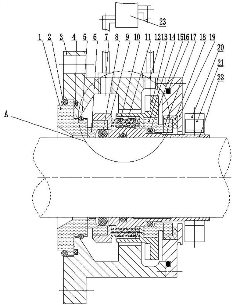
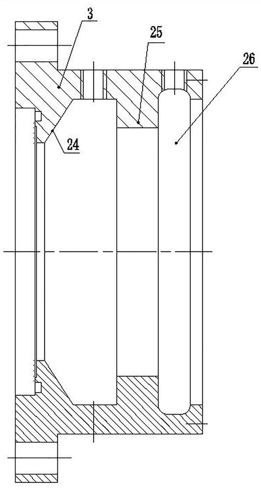
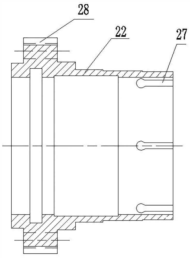
[0033] Such as Figure 1-7 As shown, a packaged self-cooling cycle mechanical seal, a packaged self-cooling cycle mechanical seal, includes a mechanical seal cover 3, a cooling water inlet 7 and a cooling water outlet 12 are opened on the mechanical seal cover 3, and the mechanical seal One side of the cover 3 is equipped with the first static ring 1, and the other side of the mechanical seal cover 3 is fastened with the second static ring seat 19 by bolts, and the second static ring seat 19 and the mechanical seal cover 3 are equipped with the second static ring seat 19. Two static ring O type rings 16 are used for sealing cooling water. The mechanical seal cover 3 is equipped with an elastic limit assembly, and one side of the first static ring 1 is equipped with an anti-loosening O-ring 5 , and an anti-loosening inclined surface 24 is provi...


PUM


Abstract

The invention belongs to the field of mechanical seals for pumps, and discloses an integrated packaging type self-cooling circulation mechanical seal to solve the technical problems existing in corrosion-resistant chemical pump centrifugal pump mechanical seals in the prior art. The mechanical seal comprises a mechanical seal cover, a first static ring is installed on one side of the mechanical seal cover, and a second static ring seat is installed on the other side of the mechanical seal cover. An elastic limiting assembly is arranged in the mechanical seal cover, a first movable ring is arranged on the inner side of a first static ring, a first movable ring seat is clamped on the first movable ring, a second static ring is arranged on the inner side of a second static ring seat, a second movable ring is arranged on the inner side of the second static ring, and a second movable ring seat is clamped on the second movable ring. The elastic limiting assembly is used for limiting the first moving ring seat and the second moving ring seat, the second moving ring seat is provided with blades, and a cooling channel is formed among a cooling water inlet, the first movable ring seat, the second movable ring seat and a cooling water outlet. The integrated packaging type self-cooling circulation mechanical seal is convenient to install, space is saved, the whole structure is compact and simple, and meanwhile cost is saved.

Description

technical field [0001] The invention relates to the field of mechanical seals for pumps, in particular to a cartridge type self-cooling cycle mechanical seal. Background technique [0002] Corrosion-resistant chemical pumps usually use externally mounted mechanical seals, because the metal parts of this type of mechanical seal are not in contact with the conveying medium, thereby improving its service life and scope of use, but if it is under crystallization and intermittent operation conditions , due to crystallization, the cooling channel is blocked, and the mechanical seal cannot be cooled, which will damage it. If ordinary mechanical seals are used, it is inevitable that metal parts will be soaked in the conveying medium, which requires high corrosion resistance of metal parts, and each metal can only withstand one kind of corrosive medium, which means There are more forms of mechanical seals, resulting in inventory pressure. In addition, it is often encountered that t...

Claims


Application Information

Patent Timeline
IPC IPC(8): F04D29/12F04D29/58F04D29/62
CPCF04D29/126F04D29/5886F04D29/628
Inventor 任振林吴志军陈春生
Owner 鸿浩泵业有限公司
Learn More