Dehumidifier with upper water tank

A technology for dehumidifiers and water tanks, which is applied to mechanical equipment, prevention of condensed water, household heating, etc. It can solve problems such as water entering the machine, difficulty in taking out the water tank, and affecting the normal use of the dehumidifier

Pending Publication Date: 2021-07-30
JIANGSU YOAU ELECTRIC CO LTD
View PDF0 Cites 2 Cited by
  • Summary
  • Abstract
  • Description
  • Claims
  • Application Information

AI Technical Summary

Problems solved by technology

Because the water tank is arranged under the machine, the water level in the water tank is not visually intuitive enough; at the same time, when the water in the water tank is full, it is difficult to take o...

Method used


Image

  • Dehumidifier with upper water tank
  • Dehumidifier with upper water tank
  • Dehumidifier with upper water tank

Examples


Embodiment 1

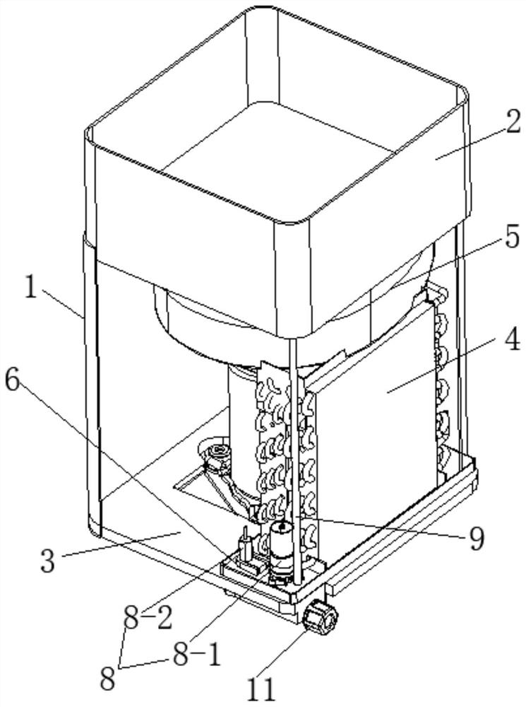
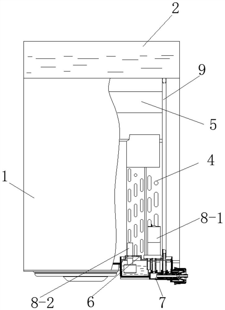
[0038] Such as Figure 1 to Figure 4 The upper water tank dehumidifier shown includes a casing 1 and a water tank 2 fixedly installed on the top of the casing 1. The inside of the casing 1 is fixedly installed with a water pan 3, a heat exchange device 4 and a fan system 5 from bottom to top. The water tray 3 is provided with a drainage system that communicates with the water tank 2 and the outside respectively. By fixing the water tank 2 on the top of the casing 1, a dehumidifier with a more beautiful appearance can be realized. Compared with the traditional dehumidifier, the water tank 2 is set on the top, the water level is more intuitive, and it is more convenient to pour water. A drainage system is installed to realize multiple drainage methods, which will not cause water to enter the machine or wet the floor, ensuring that the dehumidifier can be used normally.

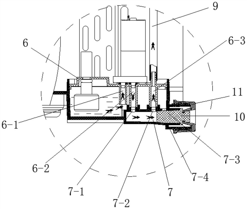
[0039] The drainage system includes a water tray cover 6, a water discharge channel 7, an automatic drainage...

Embodiment 2

[0044] Such as Figure 5 to Figure 6 As shown, the structure of this embodiment is similar to that of Embodiment 1, except that the outlet of the water discharge channel 7 is provided with a joint 12 communicating with the outside. The outer peripheral surface of the joint 12 is provided with a first annular groove 12-1, a second annular groove 12-2, a second annular limiting boss 12-3 and a second annular buckle matched with the thread buckle 11. port 12-4, the joint 12 is detachably connected to the threaded port 7-4 through the threaded buckle 11, which is convenient for installation. Both the first annular groove 12-1 and the second annular groove 12-2 are sleeved with an O-ring or an annular rubber gasket. When the second annular limiting boss 12-3 is in contact with the outlet end of the water discharge channel 7, the first annular groove 12-1 is located between the first through hole 7-1 and the second through hole 7-2, The second annular groove 12-2 is located on the...

Embodiment 3

[0046] Such as Figure 7 As shown, the structure of this embodiment is similar to that of Embodiment 1, except that the outlet of the water discharge channel 7 is provided with a second external water pipe 14 communicating with it, and the bottom of the water discharge channel 7 is lower than the bottom of the water tray 3 . When the automatic drainage device 8 is closed, the condensed water in the water tray 3 enters the water discharge channel 7 through the third through hole 6-3 due to the gravity of the water level difference, and then naturally drains to the outside through the second external water pipe 14. Since the bottom of the water discharge channel 7 is lower than the bottom of the water tray 3, it is ensured that the condensed water in the water tray can be completely discharged, especially when there is sewage in the water tray after long-term use, or when the water tray needs to be cleaned, this embodiment can be used The drainage method discharges the sewage. ...


PUM


Abstract

The invention discloses a dehumidifier with an upper water tank. The dehumidifier comprises a machine shell and the water tank, and the water tank is fixedly mounted on the top of the machine shell; a water pan, a heat exchange device and a fan system are fixedly mounted in the machine shell from bottom to top; a drainage system achieving communicating of the water tank and the outside is arranged on the water pan; and the drainage system is suitable for draining water in the water pan to the water tank or the outside. According to the dehumidifier, the appearance is more attractive, as the water tank is arranged on the upper portion, the water level is more visual, water pouring is more convenient, meanwhile, multiple drainage modes are achieved, different use requirements are met, water cannot enter the dehumidifier or wet a floor, and it is ensured that the dehumidifier can be normally used.

Description

technical field [0001] The invention relates to the technical field of dehumidifiers, in particular to a dehumidifier with an upper water tank. Background technique [0002] Dehumidifiers, also known as dehumidifiers, dryers or dehumidifiers, are a member of the air-conditioning family. Usually, a conventional dehumidifier consists of a compressor, a heat exchanger, a fan, a water tank, a casing and a controller. Its working principle is that the humid air is sucked into the machine by the fan, and passes through the heat exchanger. At this time, the water molecules in the air are condensed into water droplets, and the dried air after treatment is discharged outside the machine. This cycle keeps the indoor humidity at a suitable relative temperature. Humidity, used in occasions with high ambient humidity can quickly reduce room humidity. [0003] The water tanks of existing dehumidifiers in the market are all located under the machine, and the condensed water generated by ...

Claims


Application Information

Patent Timeline
IPC IPC(8): F24F3/14F24F11/64F24F13/22
CPCF24F3/14F24F13/222F24F11/64
Inventor 陆军侯成才
Owner JIANGSU YOAU ELECTRIC CO LTD
Why Eureka
Try Eureka