
A micro-element-based cable joint and body conductor temperature calculation method

A technology of cable joint and conductor temperature, applied in the field of conductor temperature calculation of cable joint and body, can solve problems such as direct use by unprofessional personnel, large conductor temperature error, increase and other problems, to reduce time and energy, radial heat accurate effect

Active Publication Date: 2022-07-29
GUANGZHOU POWER SUPPLY BUREAU GUANGDONG POWER GRID CO LTD
View PDF3 Cites 0 Cited by
  • Summary
  • Abstract
  • Description
  • Claims
  • Application Information

AI Technical Summary

Problems solved by technology

[0004] The existing numerical calculation method uses software such as finite element to carry out simulation calculation, and the modeling process is complicated, which is not conducive to the direct use of non-professional personnel;
[0005] The existing cable joint heat circuit model calculates the temperature distribution, its calculation accuracy is low, and the error between the calculation result and the actual conductor temperature is large;
[0006] It is very difficult to realize real-time online monitoring of cable joint conductor temperature, and it is difficult to guarantee the accuracy of temperature monitoring results in the environment of strong electromagnetic interference, which is not conducive to the improvement of the current carrying capacity of cable lines

Method used


Image

  • A micro-element-based cable joint and body conductor temperature calculation method
  • A micro-element-based cable joint and body conductor temperature calculation method
  • A micro-element-based cable joint and body conductor temperature calculation method

Examples


no. 1 example ;

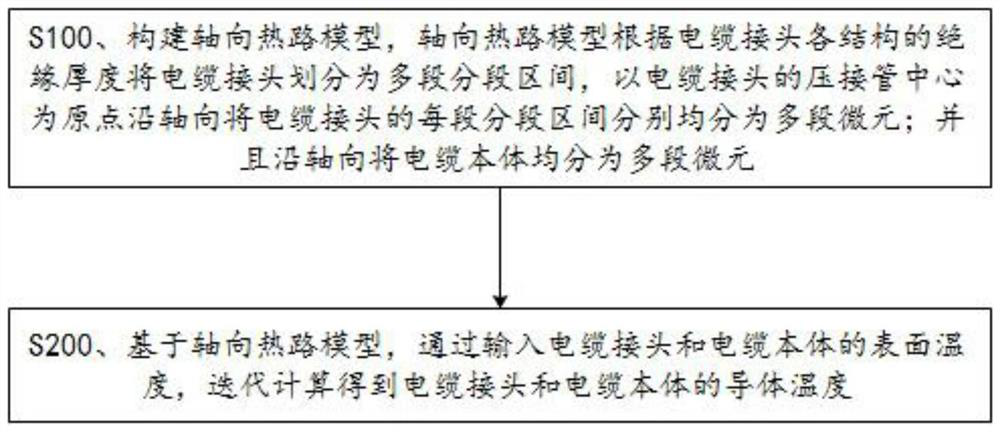
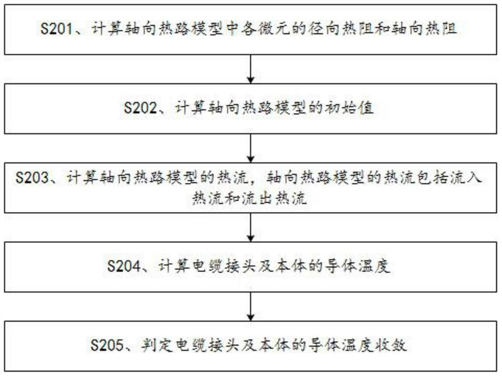
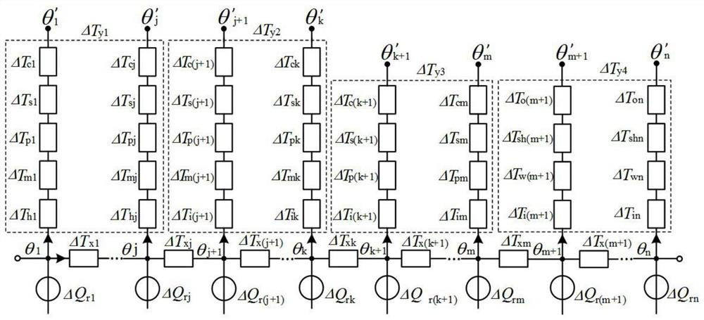
[0026] refer to Figure 1 to Figure 3 , an embodiment of the present invention provides a method for calculating the conductor temperature of a micro-element-based cable joint and body, which is used to calculate the conductor temperature of the cable joint and the cable body adjacent to the cable joint, including the following steps:

[0027] S100. Build an axial thermal path model. The axial thermal path model divides the cable joint into multi-segment sections according to the insulation thickness of each structure of the cable joint, and takes the center of the crimping tube of the cable joint as the origin to divide each section of the cable joint in the axial direction. The segment interval is divided into multi-segment micro-elements respectively; and the cable body is equally divided into multi-segment micro-elements along the axial direction.

[0028] It should be noted that, because the structure of the cable joint is axisymmetric, and the structure of the long end a...

no. 2 example ;

[0080] In order to verify the effect of the embodiment of the present invention, a set of experimental data is provided below:

[0081] To adapt to 110kV 630mm 2 The straight-through joint of the cable, the line current carrying capacity is 1000A as an example, the axial thermal circuit model proposed in the embodiment of this method is used to calculate the conductor temperature, and the theoretical calculation results and simulation calculation results are calculated. The results of the method are compared, and the results are as follows Figure 4 shown. In the experiment, the distance of each micro-element is as follows:

[0082] The micro-element lengths of short-end crimping tube, short-end main insulation, short-end copper shell thin layer, and short-end body are 0.098m, 0.071m, 0.075m, and 0.1257m respectively; long-end crimping tube, long-end main insulation, long-end The micro-element lengths of the copper shell thin layer and the long-end body are 0.098m, 0.082m, ...

no. 3 example ;

[0085] refer to Figure 5 , an embodiment of the present invention provides a micro-element-based cable joint and body conductor temperature calculation device, the micro-element-based cable joint and body conductor temperature calculation device can be any type of smart terminal, such as a mobile phone , Tablet PC, Personal Computer, etc.

[0086] Specifically, the device for calculating the conductor temperature of the micro-element-based cable joint and body includes: one or more control processors and a memory. The control processor and memory may be connected by a bus or otherwise.

[0087] As a non-transitory computer-readable storage medium, the memory can be used to store non-transitory software programs, non-transitory computer-executable programs, and modules, such as the micro-element-based cable joint and the conductors of the body in the embodiment of the present invention Program instructions / modules corresponding to the temperature computing device. The contr...


PUM


Abstract

The invention discloses a method for calculating the conductor temperature of a cable joint and a body based on micro-elements. The method includes: constructing an axial thermal circuit model, and the axial thermal circuit model divides the cable joint into multiple sections according to the insulation thickness of each structure of the cable joint. In the segment interval, with the center of the crimping tube of the cable joint as the origin, each segment of the cable joint is divided into multi-segment micro-elements in the axial direction; and the cable body is equally divided into multi-segment micro-elements in the axial direction; based on the axial thermal The road model, by inputting the surface temperature of the cable joint and the cable body, iteratively calculates the conductor temperature of the cable joint and the cable body. Compared with the prior art, the calculation result of the present invention is more accurate, and the calculation result can be obtained only by inputting the surface temperature of the cable joint and the body in the model, which takes less time and effort, and also solves the difficulty of sensor arrangement. problem.

Description

technical field [0001] The invention relates to the technical field of temperature measurement of conductors of cable joints, in particular to a method for calculating the temperature of conductors of cable joints and bodies based on micro-elements. Background technique [0002] With the rapid development of urban power grid systems, high-voltage power cables have been widely used in power transmission networks, and the number of intermediate joints used to connect cables at both ends is also increasing. The cable current carrying capacity is closely related to the conductor temperature. Practical experience has proved that due to the thick insulation of the cable joint and the internal contact resistance, the temperature of the cable joint conductor is much higher than that of the cable conductor under the same load level, which has become a bottleneck restricting the current carrying capacity of the line. [0003] At present, the analytical method and numerical calculation...

Claims


Application Information

Patent Timeline
Patent Type & Authority Patents(China)
IPC IPC(8): G06F30/20G06F111/04G06F111/10G06F113/04G06F113/16G06F119/08
CPCG06F30/20G06F2111/04G06F2111/10G06F2119/08G06F2113/16G06F2113/04
Inventor 卞佳音肖健健苏俊亮张珏单鲁平慕容啟华徐研马世禄顾侃贺伟蚁暄潮黄明烽
Owner GUANGZHOU POWER SUPPLY BUREAU GUANGDONG POWER GRID CO LTD
Learn More