
Fan rotating speed recovery control method, controller and wind power plant

A technology of fan speed and recovery control, applied in wind power generation, electrical components, circuit devices, etc., can solve problems such as failure to achieve rotor speed recovery and affecting the stability of the AC system at the receiving end.

Active Publication Date: 2021-07-30
HUAZHONG UNIV OF SCI & TECH
View PDF6 Cites 1 Cited by
  • Summary
  • Abstract
  • Description
  • Claims
  • Application Information

AI Technical Summary

Problems solved by technology

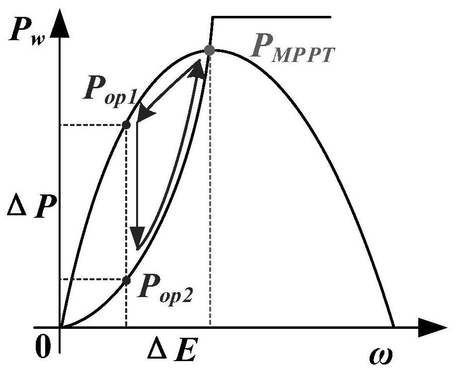
[0004] Since the existing control strategy only uses the maximum power point curve to constrain the power and speed of the fan, it may not be possible to recover the rotor speed, and it may also cause the secondary frequency drop of the AC system frequency at the receiving end to be more serious than the primary frequency drop , affecting the stability of the entire AC system at the receiving end

Method used


Image

  • Fan rotating speed recovery control method, controller and wind power plant
  • Fan rotating speed recovery control method, controller and wind power plant
  • Fan rotating speed recovery control method, controller and wind power plant

Examples


Embodiment 1

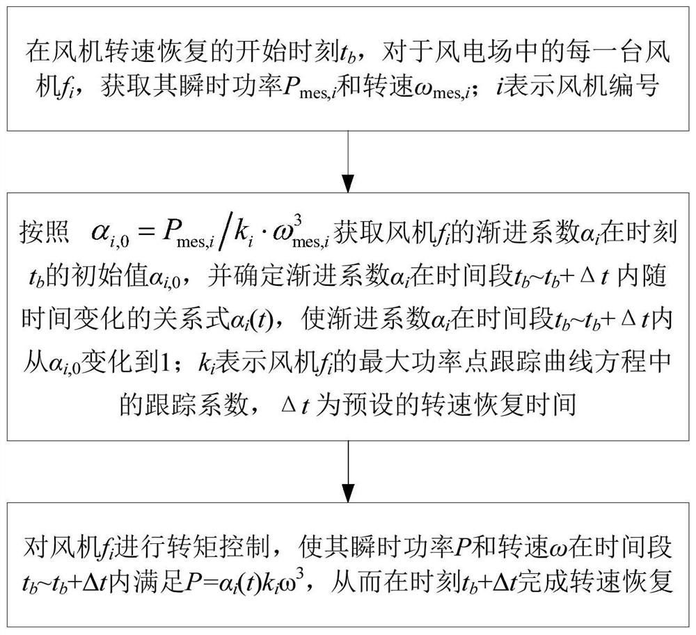
[0037] A fan speed recovery control method, such as figure 2 shown, including:

[0038] At the start time t of fan speed recovery b , for each wind turbine f in the wind farm i , to obtain its instantaneous power P mes,i and speed ω mes,i ;i represents the fan number;

[0039] according to get fan f i Asymptotic coefficient α i at time t b initial value of α i,0 , and determine the asymptotic coefficient α i in time period t b ~t b Time-varying relationship α in +Δt i (t), so that the asymptotic coefficient α i in time period t b ~t b +Δt from α i,0 change to 1; k i Indicates fan f i The maximum power point tracking curve equation (that is, P=k i ω 3 ) in the tracking coefficient; for a given fan, k i is a known parameter; Δt is the preset speed recovery time;

[0040] For fan f i Perform torque control so that the instantaneous power P and speed ω are in the time period t b ~t b Satisfy P=α within +Δt i (t)k i ω 3 , so that at time t b +Δt compl...

Embodiment 2

[0053] A fan speed recovery controller, including: a data acquisition module, a data processing module and a control module;

[0054] The data acquisition module is used for starting time t when the fan speed recovers b , to obtain the instantaneous power P of the fan mes,i and speed ω mes,i , and trigger the data processing module;

[0055] data processing module for following get fan f i Asymptotic coefficient α i at time t b initial value of α i,0 , and determine the asymptotic coefficient α i in time period t b ~t b Time-varying relationship α within +Δt i (t), so that the asymptotic coefficient α i in time period t b ~t b +Δt from α i,0 Change to 1, then trigger the control module; k i Indicates the tracking coefficient in the maximum power point tracking curve equation of the fan, and Δt is the preset speed recovery time;

[0056] The control module is used to control the torque of the fan so that its instantaneous power P and speed ω are in the time per...

Embodiment 3

[0061] A wind farm includes a plurality of wind turbines, and each wind turbine is equipped with the wind speed restoration controller provided in the above-mentioned embodiment 2.

[0062] Those skilled in the art should understand that the embodiments of the present invention may be provided as methods, systems, or computer program products. Accordingly, the present invention can take the form of an entirely hardware embodiment, an entirely software embodiment, or an embodiment combining software and hardware aspects. Furthermore, the present invention may take the form of a computer program product embodied on one or more computer-usable storage media (including but not limited to disk storage, CD-ROM, optical storage, etc.) having computer-usable program code embodied therein.


PUM


Abstract

The invention discloses a fan rotating speed recovery control method, a controller and a wind power plant, and belongs to the field of electric power system control, and the method comprises the steps: obtaining the instantaneous power Pmes,i and the rotating speed omega mes,i of each fan fi in the wind power plant at the starting moment tb of fan rotating speed recovery; acquiring an initial value alpha i,0 of a progressive coefficient alpha i of the fan fi at a moment tb, and determining a relational expression alpha i(t) of the progressive coefficient alpha i along with time change in a time period tb-tb+delta t, so that the progressive coefficient alpha i is changed from alpha i,0 to 1 in the time period tb-tb+delta t; ki representing a tracking coefficient in the maximum power point tracking curve equation of the fan fi, and delta t being preset rotating speed recovery time; conducting torque control on the fan fi, so that the instantaneous power P and the rotating speed omega of the fan fi meet the condition that P=alphai(t)kiomega3 within the time period tb-tb+delta t, and rotating speed recovery is completed at the moment tb+delta t. According to the method, smooth rotating speed recovery can be carried out after the fan provides frequency support, so that the problem of secondary frequency drop of a receiving end alternating current system is relieved.

Description

technical field [0001] The invention belongs to the field of electric power system control, and more specifically, relates to a fan speed recovery control method, a controller and a wind farm. Background technique [0002] In recent years, wind farms, especially large-scale offshore wind farms, are becoming a hot spot for the development of clean energy. Since wind farms are usually far away from the AC system at the receiving end, long-distance and large-capacity power transmission is required. From a technical and economic point of view, The voltage source converter-based multi-terminal direct current (VSC-MTDC) transmission system is an ideal way for wind farms to be connected to the grid. Due to the decoupling control between the multi-terminal flexible DC electromechanical systems, the wind farm cannot directly respond to the frequency deviation of the receiving-end AC system, and the system rate of change of frequency (RoCoF) may increase rapidly with the increase of w...

Claims


Application Information

Patent Timeline
Patent Type & Authority Applications(China)
IPC IPC(8): H02J3/24H02J3/38
CPCH02J3/24H02J3/381H02J2300/28Y02E10/76
Inventor 姚伟熊永新艾小猛文劲宇林思齐
Owner HUAZHONG UNIV OF SCI & TECH
Learn More