Large-scale permanent magnet energy generator

A permanent magnet, large-scale technology, applied in the direction of electromechanical devices, electrical components, etc., can solve the problems of nuclear power plant safety hazards, limited energy saving effect, and inability to generate power continuously and stably.

Pending Publication Date: 2021-07-30
胡小杰
View PDF0 Cites 1 Cited by
  • Summary
  • Abstract
  • Description
  • Claims
  • Application Information

AI Technical Summary

Problems solved by technology

Nuclear power plants are expensive and unsafe. In case of earthquakes or wars, nuclear power plants are the biggest safety hazard
Although wind power and photovoltaic power generation are good, they cannot generate electricity continuously and stably due to the impact of climate change, which has brought great trouble to the transmission plan of power grid companies; All permanent magnet motors have coil windings inside, and only a small amount of permanent magnets are placed in the rotor or stator. Although these permanent magnet motors can save energy, the energy saving effect is very limited, at most no more than 15%, and the proportion of energy consumption is still very high. big

Method used


Image

  • Large-scale permanent magnet energy generator
  • Large-scale permanent magnet energy generator
  • Large-scale permanent magnet energy generator

Examples


Embodiment Construction

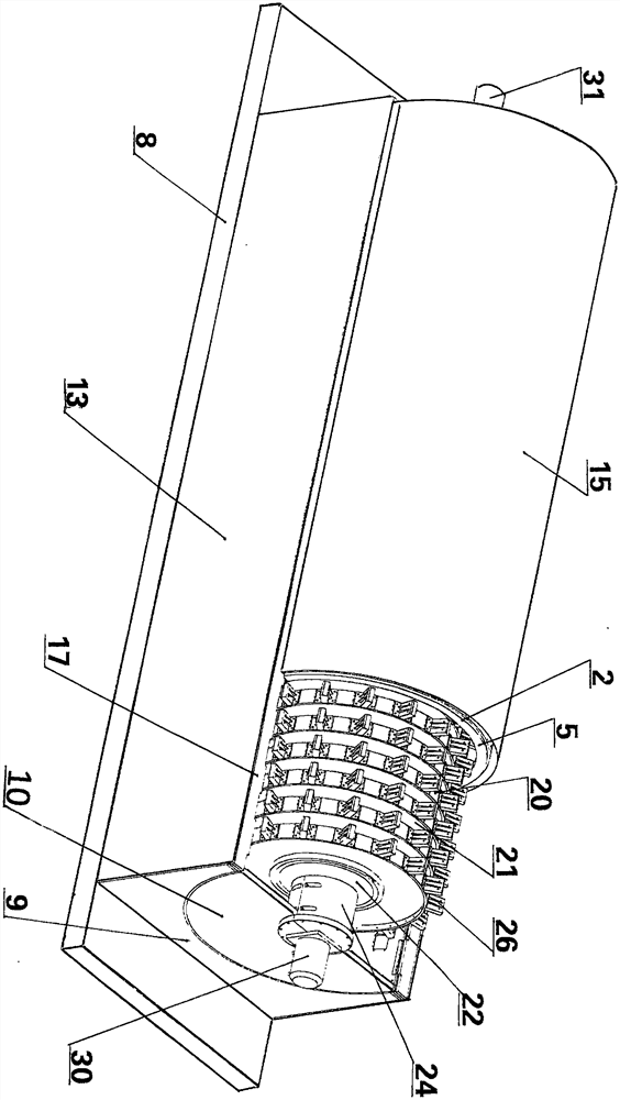
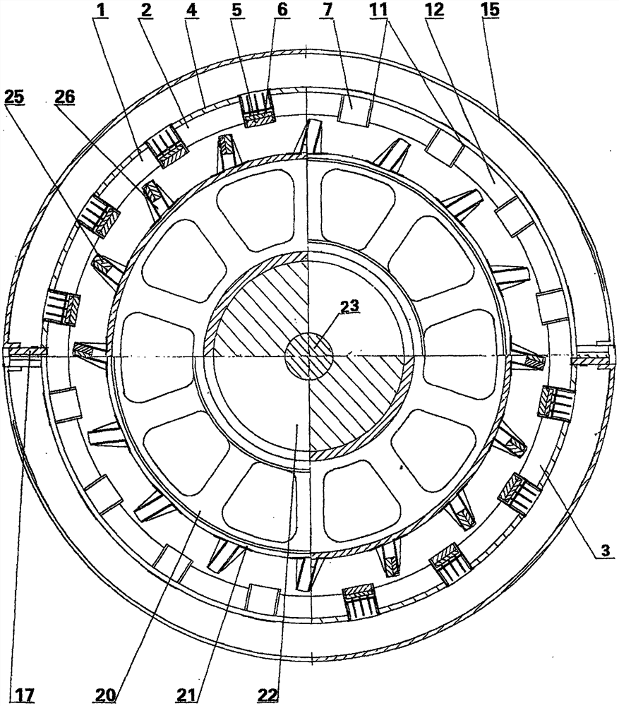
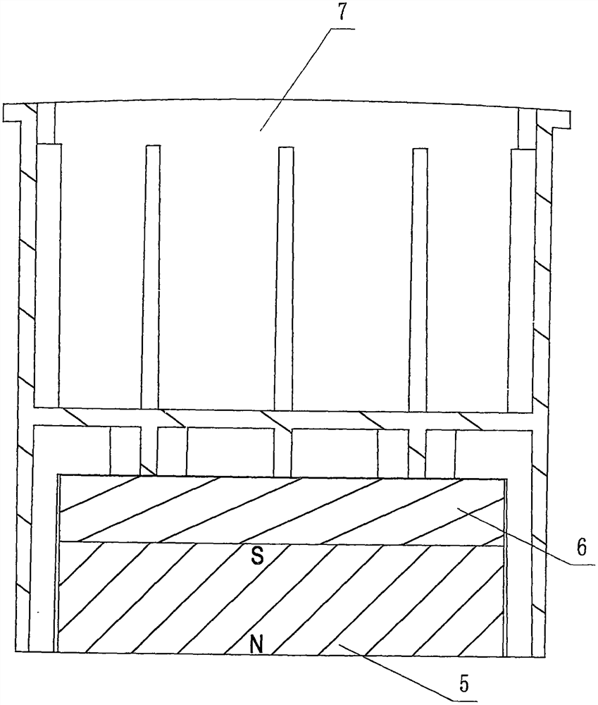
[0020] The present invention will be further described in detail below with reference to the embodiments of the accompanying drawings.

[0021] like Figure 1 to Figure 8 Shown is a schematic diagram of the structure of the present invention, wherein the reference numerals are: stator 1, upper half stator 2, lower half stator 3, stator magnetic separation area 4, stator permanent magnet 5, stator ferromagnetic block 6, stator permanent magnet fixed box 7. Stator chassis 8, stator fixing frame 9, stator center positioning plate 10, center distance 11, stator reinforcing ribs 12, stator side cover 13, stator top cover 15, upper half stator pressure plate 17, rotor 20, rotor magnetic partition frame 21 , rotor hollow main shaft 22, main shaft journal 23, rotor bearing seat 24, rotor permanent magnet 25, rotor permanent magnet fixing box 26, rotor ferromagnetic block 27, bearing bush 28, rotor axial displacement cylinder 30, power output shaft 31. Power output spline shaft 38, ma...


PUM


Abstract

The invention discloses a large-scale permanent magnet energy generator, which comprises a stator, a rotor and a rotor axial displacement device, wherein the stator and the rotor are respectively provided with a plurality of magnetic separation areas in the axial direction, a plurality of stator permanent magnet fixing boxes with built-in stator permanent magnets are uniformly distributed in the circumference of the stator magnetic separation area, a plurality of rotor permanent magnet fixing boxes with built-in rotor permanent magnets are uniformly distributed outside the circumference of the rotor magnetic separation area, the permanent magnets in the stator are axially arranged in each row to form a line, and the permanent magnets in the rotor are axially arranged in each row in a spiral shape, so that the rotor permanent magnets form a rotating magnetic field which can circularly attract the stator permanent magnets to drive the rotor to rotate; the rotor axial displacement device is used for controlling the rotating speed and the power of the rotor and can also be used for controlling the stopping or starting time of the rotor; and according to the large-scale permanent magnet energy generator, external energy input is not needed, high-power mechanical energy is manufactured by relying on magnetic energy of hundreds of pairs of stator permanent magnets and rotor permanent magnets through a certain technical scheme, and the high-power permanent magnet energy generator can drive a large generator to generate electricity, drive vehicles and ships to run and the like.

Description

technical field [0001] The invention relates to a mechanical energy manufacturing device, in particular to a large-scale permanent magnet energy generator, in particular to a magnetic energy using thousands of strong magnetic permanent magnets, which can be continuously manufactured through a certain technical scheme. High-power mechanical energy, it can drive large generators to generate electricity, drive cars, ships, etc. Background technique [0002] The energy problem is an urgent problem to be solved in the world. Oil and coal will be exhausted, and energy will be increasingly scarce. The biggest energy crisis that people will face is not far away. my country is a big energy-consuming country. About 60% of its oil is imported. my country's carbon dioxide emissions are also one of the largest in the world. The carbon dioxide emitted by coal power plants and fuel vehicles has seriously polluted most of the sky over China. It has caused great harm to the physical and ment...

Claims


Application Information

Patent Timeline
Patent Type & Authority Applications(China)
IPC IPC(8): H02K53/00
CPCH02K53/00
Inventor 胡小杰
Owner 胡小杰
Why Eureka
Try Eureka