
Circulating current suppression direct prediction control method and system for parallel converter cluster

A circulation suppression and predictive control technology, applied in the direction of converting AC power input to DC power output, output power conversion devices, electrical components, etc., can solve the difficulties of multi-objective control, slow dynamic response, and nonlinear constraint optimization, etc. question

Active Publication Date: 2021-07-30
SHANDONG UNIV
View PDF14 Cites 2 Cited by
  • Summary
  • Abstract
  • Description
  • Claims
  • Application Information

AI Technical Summary

Problems solved by technology

However, the disclosed schemes have defects such as slow dynamic response, difficult realization of multi-objective control, and difficult optimization of nonlinear constraints.

Method used


Image

  • Circulating current suppression direct prediction control method and system for parallel converter cluster
  • Circulating current suppression direct prediction control method and system for parallel converter cluster
  • Circulating current suppression direct prediction control method and system for parallel converter cluster

Examples


Embodiment 1

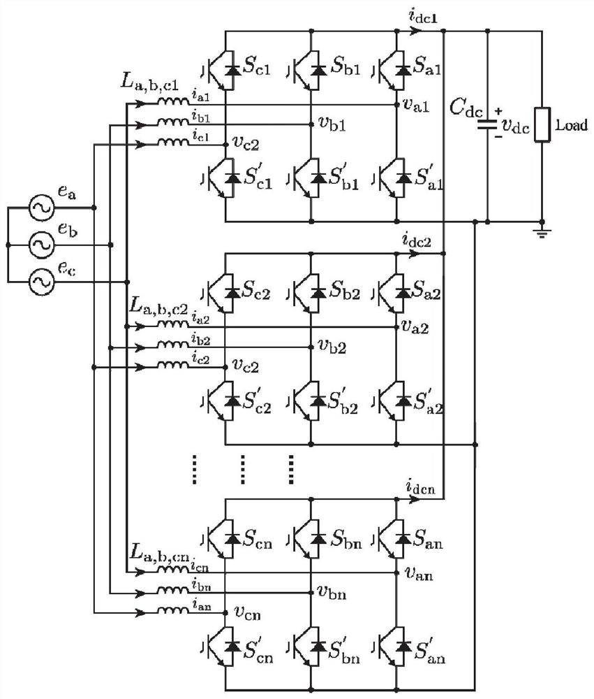
[0046] This embodiment discloses a direct predictive control method for circulating current suppression of a parallel converter cluster. In order to illustrate the above solution, the parallel converter cluster is described as follows:

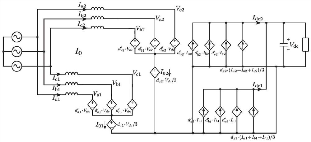
[0047] See attached figure 1 Shown is the circuit topology diagram of the power converter of the parallel converter cluster of the present invention. The power circuit mainly realizes the transformation of electric energy form from AC to DC, and the energy can realize bidirectional flow. The stand-alone power converter takes the three-phase two-level topology as an example, including the three-phase inductor L a =L b =L c =L, parasitic resistance R a =Rb = R c = R; three-phase full-bridge power switch S a , S′ a , S b , S′ b , S c , S′ c ; DC bus capacitance C dc . Multiple converters are connected in parallel, that is, the AC sides are commonly connected to the three-phase AC bus (grid), and the DC sides are commonly connected to...

Embodiment 2

[0098] The purpose of this embodiment is to provide a computing device, which includes a memory, a processor, and a computer program stored in the memory and operable on the processor. The processor implements the steps of the above control method when executing the program.

Embodiment 3

[0100] The purpose of this embodiment is to provide a computer-readable storage medium.

[0101] A computer-readable storage medium, on which a computer program is stored, and when the program is executed by a processor, the steps of the above control method are executed.


PUM


Abstract

The invention provides a circulating current suppression direct prediction control method and system for a parallel converter cluster. The method comprises the following steps of: obtaining a three-phase current value of a converter cluster at the current moment, and carrying out coordinate transformation and delay compensation; predicting a current value at a subsequent moment according to the compensated three-phase current value, calculating cost functions according to the predicted value, comparing all the cost functions, and selecting a voltage vector minimizing the values of the cost functions as an optimal voltage vector; for the compensated three-phase current value, calculating a zero-sequence circulating current, and selecting a zero voltage vector according to the direction of the zero-sequence circulating current at the current moment k; and according to the obtained optimal voltage vector and the zero voltage vector, constructing a synthetic voltage vector, and obtaining a switching signal sent to the converters to eliminate the circulating current. On the premise of accurately controlling the output current, the zero-sequence circulating current between the parallel converters can be effectively eliminated.

Description

technical field [0001] The disclosure belongs to the technical fields of new energy grid connection, smart microgrid, and power electronic energy conversion, and in particular relates to a direct predictive control method and system for circulation suppression of parallel converter clusters. Background technique [0002] The statements in this section merely provide background information related to the present disclosure and do not necessarily constitute prior art. [0003] Building a low-carbon, high-efficiency energy system is the core goal of my country's energy transformation, and new energy access and energy conversion are the key means to achieve this goal. In recent years, the scale of new energy has been continuously expanded, and the power level of energy conversion and transmission has been continuously improved. Therefore, there is an urgent need to develop and design high-power power electronic converter equipment. In order to solve the above problems, there ar...

Claims


Application Information

Patent Timeline
IPC IPC(8): H02M7/219H02M1/32H02M1/088H02H7/10H02J3/38
CPCH02M7/219H02M1/32H02M1/088H02H7/10H02J3/38
Inventor 张祯滨李昱李真何汉孙远翔
Owner SHANDONG UNIV
Learn More