
Power device thermal protection and early warning method and system based on junction temperature prediction

A power device, thermal protection technology, applied in the direction of automatic disconnection emergency protection device, emergency protection circuit device responding to undesired changes, emergency protection circuit device, etc. Reduce work efficiency, increase system cost, etc., to achieve the effect of improving stability and work efficiency, improving quality, and overcoming the lag effect

Active Publication Date: 2021-01-08
SHANDONG UNIV
View PDF6 Cites 0 Cited by
  • Summary
  • Abstract
  • Description
  • Claims
  • Application Information

AI Technical Summary

Problems solved by technology

Such a protection mechanism cannot give full play to the physical limits of power devices, resulting in increased system costs and reduced work efficiency

Method used


Image

  • Power device thermal protection and early warning method and system based on junction temperature prediction
  • Power device thermal protection and early warning method and system based on junction temperature prediction
  • Power device thermal protection and early warning method and system based on junction temperature prediction

Examples


Embodiment 1

[0038] In one or more embodiments, a method for thermal protection and early warning of power devices based on junction temperature prediction is disclosed, including the following process:

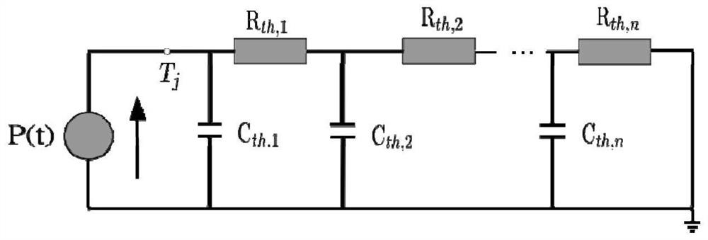
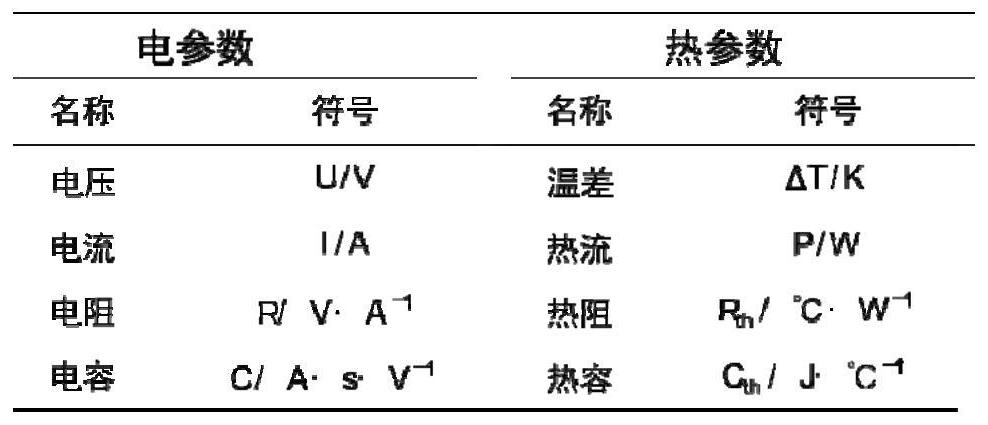
[0039] Calculate the thermal resistance and heat capacity corresponding to each layer inside the power device, and establish the corresponding Cauer thermal network model;

[0040] Establish a temperature model for the power device, and obtain the temperature inside the device through calculation. According to the state variable corresponding to the minimized cost function at n moments in the future, calculate the power consumption at n moments in the future, that is, the change trajectory of the heat flow parameter;

[0041] According to the Cauer thermal network model and the change trajectory of heat flow parameters, the junction temperature change trajectory of power devices is calculated;

[0042] Compare the calculated junction temperature change track with the warning temperature ...

Embodiment 2

[0056] In one or more embodiments, a power device thermal protection and early warning system based on power device junction temperature prediction is disclosed, including:

[0057] A device for calculating the thermal resistance and heat capacity corresponding to each layer inside the power device, and establishing the corresponding Cauer thermal network model;

[0058] A device for calculating the power consumption at n moments in the future, that is, the change track of the heat flow parameter, according to the state variables at n moments in the future corresponding to the minimized cost function;

[0059] A device for calculating the change track of the junction temperature of the power device according to the Cauer thermal network model and the change track of the heat flow parameter;

[0060] The device is used to compare the calculated junction temperature change track with the warning temperature to determine the current working state of the power device.

[0061] Th...

Embodiment 3

[0063] In one or more embodiments, a terminal device is disclosed, including a server, the server includes a memory, a processor, and a computer program stored on the memory and operable on the processor, and the processor executes the The program realizes the thermal protection and early warning method of the power device based on the junction temperature prediction in the first embodiment. For the sake of brevity, details are not repeated here.


PUM


Abstract

The invention discloses a power device thermal protection and early warning method and system based on junction temperature prediction, including: calculating the thermal resistance and heat capacity corresponding to each layer inside the power device, establishing a corresponding Cauer thermal network model; The state variables at n moments in the future are calculated to calculate the power consumption at n moments in the future, that is, the change trajectory of the heat flow parameter; according to the Cauer thermal network model and the change trajectory of the heat flow parameter, the junction temperature change trajectory of the power device is calculated; the calculated Comparing the junction temperature change track with the warning temperature to determine the current working state of the power device. The invention can protect the power device in advance within the safe time when the predicted junction temperature reaches the warning temperature, so as to ensure that the power device works in a safe temperature range.

Description

technical field [0001] The invention relates to the technical field of thermal protection of power devices, in particular to a method and system for thermal protection and early warning of power devices based on junction temperature prediction. Background technique [0002] The statements in this section merely provide background information related to the present invention and do not necessarily constitute prior art. [0003] Power electronic systems for applications such as new energy electric vehicles, smart grids, and high-performance electric drives work for a long time under harsh working conditions of high voltage, high current, strong electromagnetic interference, time-varying loads, and limited heat dissipation. The complicated changes in working conditions make the waste heat generated by power devices very different, and the temperature of the devices also fluctuates greatly, which in turn leads to frequent stress fluctuations between devices, which seriously affe...

Claims


Application Information

Patent Timeline
Patent Type & Authority Patents(China)
IPC IPC(8): H02H5/04H02H7/10G01R31/26
CPCH02H5/04H02H7/10G01R31/2642G01R31/2601H01L23/34H02J2300/28H02H6/00H03K2017/0806G01R31/40
Inventor 张祯滨张进李昱李真高峰
Owner SHANDONG UNIV
Learn More