Metal material transportation device

A technology for transportation devices and metal materials, applied in transportation and packaging, multi-axis trolleys, trolley accessories, etc., can solve problems such as inability to transport metal materials, and achieve the effect of improving efficiency

Active Publication Date: 2021-08-03
江苏格哩雅金属科技有限公司
View PDF10 Cites 1 Cited by
  • Summary
  • Abstract
  • Description
  • Claims
  • Application Information

AI Technical Summary

Problems solved by technology

[0004] In order to make up for the deficiencies of the existing technology and solve the problem that most of the existing transportation devices cannot transport metal materials well, the present invention proposes a transportation device for metal materials

Method used


Image

  • Metal material transportation device
  • Metal material transportation device
  • Metal material transportation device

Examples


Embodiment 1

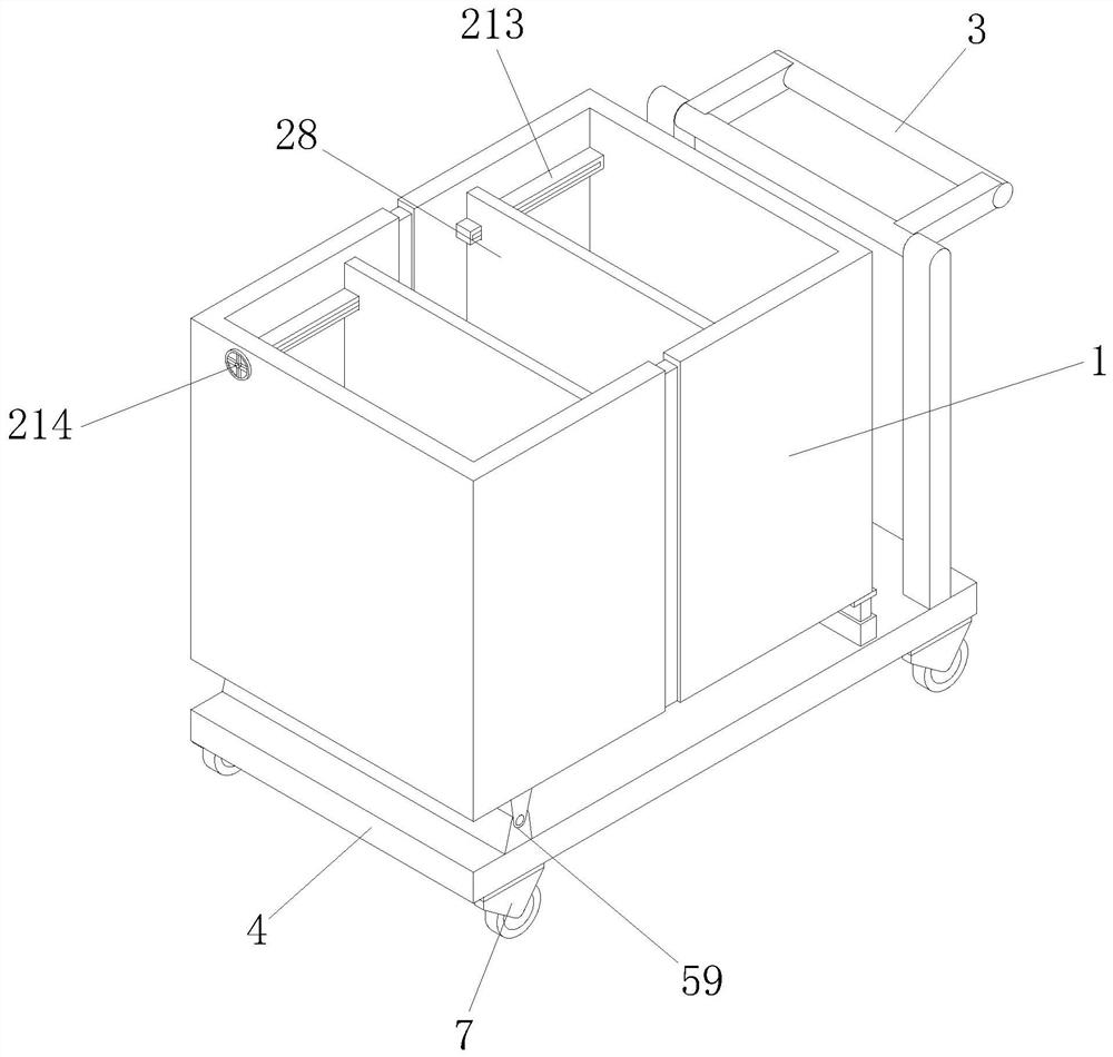
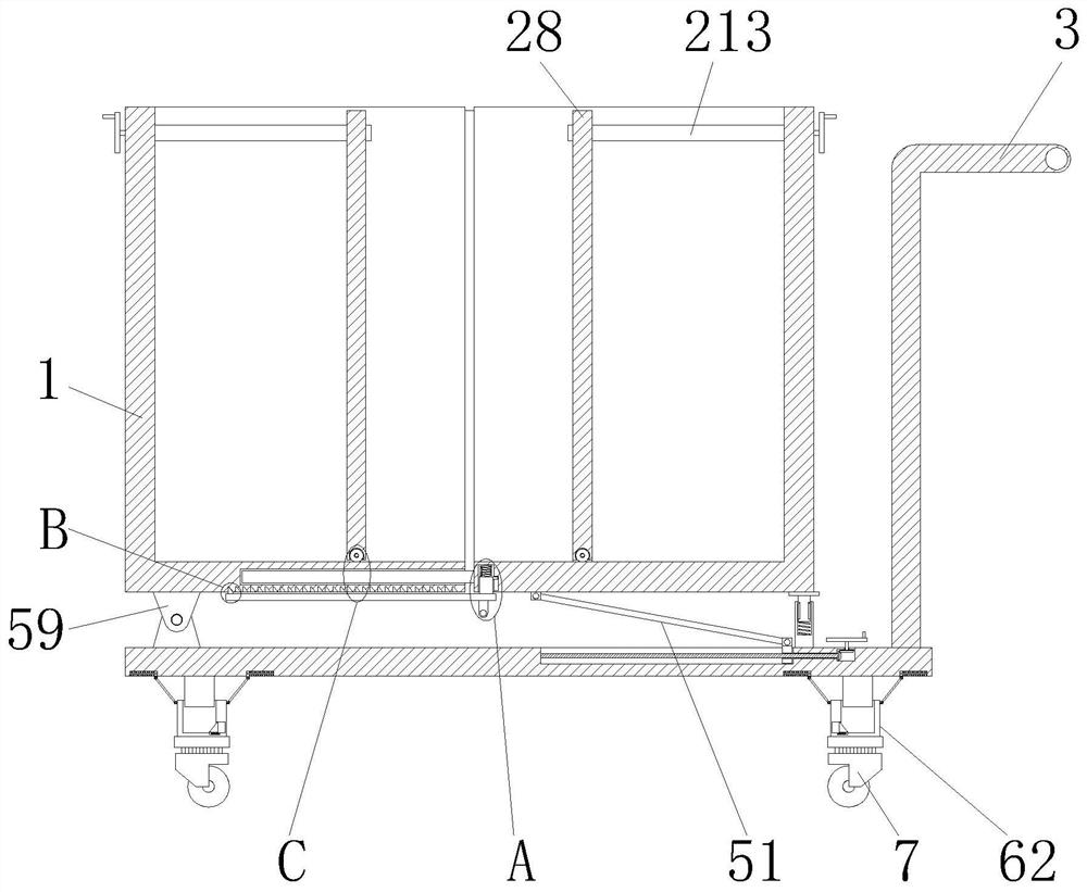
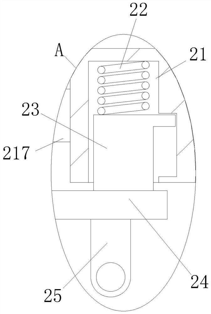
[0034] see Figure 1-14As shown, a transportation device for metal materials includes a storage bin 1, a handrail 3, a bottom plate 4 and a universal wheel 7; the storage bin 1 is provided with two groups, and the bottom ends of the storage bins 1 of the two groups are provided with a bottom plate 4. The bottom end of the storage bin 1 is provided with a base plate 4, and one side of the top end of the base plate 4 is fixedly connected with a handrail 3, and the bottom end of the base plate 4 is provided with a universal wheel 7; the inside of the storage bin 1 An adjustment mechanism is provided, and the adjustment mechanism includes a reset chamber 21, a first spring 22, a connection block 23, a connection plate 24, a block 26, a slot 27, a partition 28, a first screw sleeve 211, a first screw rod 212, Movable cavity 213, pulley 215, transmission belt 216, extension plate 217 and storage cavity 218, described reset cavity 21 is opened at the bottom end of storage bin 1 on th...

Embodiment 2

[0041] see Figure 15 As shown in Comparative Example 1, as another embodiment of the present invention, the top end of the inner side of the sleeve block 62 is fixedly connected with a third slider 613, and the third slider 613 is slidably connected to the third chute 614. Inside, the third chute 614 is provided on one side of the insert block 61; during operation, the third slider 613 moves along with the movement of the sleeve block 62, and slides inside the third chute 614 through the first The combination of the three sliding blocks 613 and the third sliding groove 614 limits the moving distance of the sleeve block 62, and at the same time, the third sliding block 613 and the third sliding groove 614 prevent the insertion block 61 from coming out of the sleeve block 62. effect.

[0042] The working principle is that when the volume of the storage bin 1 is to be enlarged, the storage bin 1 on the left side is pulled to the left, and under the action of the pulling force t...


PUM


Abstract

The invention belongs to the field of transportation devices, and particularly relates to a metal material transportation device which comprises storage bins, a handrail, a bottom plate and universal wheels. The two sets of storage bins are arranged, the bottom plate is arranged at the bottom ends of the two sets of storage bins, the handrail is fixedly connected to one side of the top end of the bottom plate, and the universal wheels are arranged at the bottom ends of the bottom plates; an adjusting mechanism is arranged in the storage bin and comprises a reset cavity, a first spring, a connecting block, a connecting plate, a clamping block, a clamping groove, a partition plate, a first threaded sleeve, a first threaded rod, a movable cavity, a belt wheel, a transmission belt, an extension plate and a storage cavity, and the reset cavity is formed in the bottom end of the storage bin on the right side; the first spring is arranged in the reset cavity, the connecting block is arranged in the reset cavity in a sleeved mode, and the connecting plate is fixedly connected with the connecting block; and the effect of adjusting the size of the storage space is achieved through the adjusting mechanism.

Description

technical field [0001] The invention relates to the field of transportation devices, in particular to a transportation device for metal materials. Background technique [0002] The transport device refers to the carrier that transports the goods from one place to another area, and plays the role of transshipment of the specified type of goods. The existing metal materials are mostly transported by general-purpose transport devices. The existing general-purpose transport After a long period of improvement, the device can better transport most items. [0003] Most of the existing transportation devices cannot transport metal materials well. Mixing metal materials with other items during transportation may cause metal-to-material damage to other items, or other items to metal materials. wear; therefore, a transport device for metal materials is proposed to address the above problems. Contents of the invention [0004] In order to make up for the deficiencies of the existing...

Claims


Application Information

Patent Timeline
Patent Type & Authority Applications(China)
IPC IPC(8): B62B3/02B62B3/04B62B5/00
CPCB62B3/02B62B3/04B62B5/0006B62B2203/10
Inventor 李波
Owner 江苏格哩雅金属科技有限公司
Why Eureka
Try Eureka