An automatic guided trolley for logistics handling

A technology that automatically guides trolleys and logistics handling. It is used in transportation and packaging, construction, mechanical conveyors, etc. It can solve the problems of small contact area and unstable cargo handling, so as to increase the contact area, improve service life, and improve flexibility. sexual effect

Active Publication Date: 2022-07-29
湖南蓝天智能物流装备有限公司
View PDF0 Cites 0 Cited by
  • Summary
  • Abstract
  • Description
  • Claims
  • Application Information

AI Technical Summary

Problems solved by technology

[0005] Aiming at the deficiencies of the prior art, the present invention provides an automatic guided trolley for logistics transportation, mainly to solve the problem that the contact area between the top plate of the existing automatic guided trolley and the cargo is small and easily lead to unstable cargo transportation

Method used


Image

  • An automatic guided trolley for logistics handling
  • An automatic guided trolley for logistics handling
  • An automatic guided trolley for logistics handling

Examples


Embodiment 1

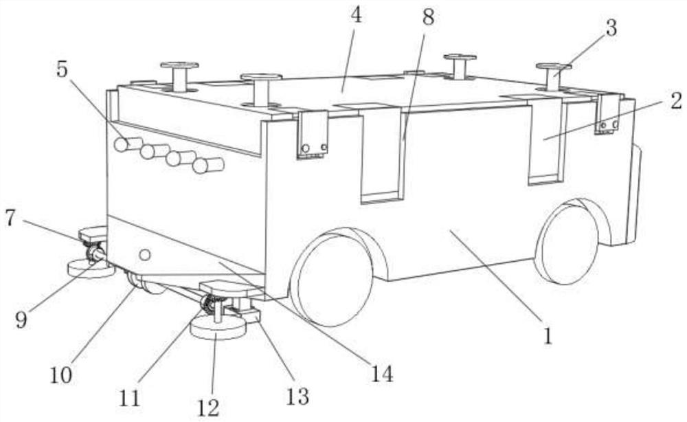
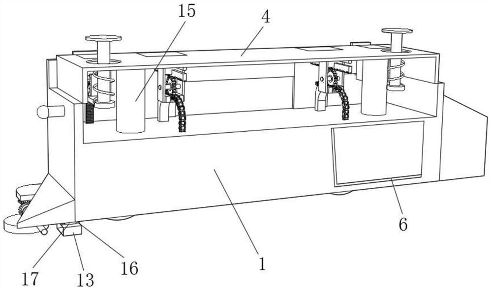
[0033] refer to Figure 1-Figure 5 , an automatic guide trolley for logistics handling, comprising a car body 1, a plurality of electric telescopic rods 15 are fixed on the bottom inner wall of the car body 1 by bolts, the top of the electric telescopic rods 15 is fixed with a top frame 4 by bolts, and the Two notches 8 are opened on both sides, and two extension mechanisms 2 are provided on both sides of the vehicle body 1. The extension mechanism 2 includes a fixing frame 26. The fixing frame 26 is fixed to the bottom of the top frame 4 by bolts. The fixing frame 26 Two sliding holes are opened on one side of the sliding hole, and the first rack 25 and the guide rod 27 are respectively slidably connected in the sliding holes. A connecting shaft is fixed with bolts on one side, a first gear 28 is rotatably connected to one side of the connecting shaft, and the first gear 28 is meshed with the first rack 25 , and the bottom of the fixing frame 26 is fixed with a guide block 21...

Embodiment 2

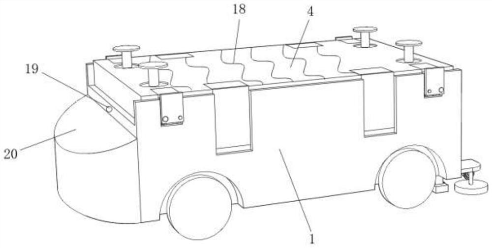
[0037] refer to Image 6 , an automatic guiding trolley for logistics handling, further comprising two first telescopic rods 41, the first telescopic rods 41 are fixed on one side outer wall of the vehicle body 1 by bolts, and one end of the first telescopic rods 41 is fixed with a buffer plate by bolts 43. When the device collides with an external object, the object presses the buffer plate 43 to shrink the first telescopic rod 41, so as to buffer the device and prevent the device from being damaged by the impact of external objects. One side of the first telescopic rod 41 The first spring 42 is sleeved, and the two ends of the first spring 42 are respectively fixed with the buffer plate 43 and the vehicle body 1. When the object leaves the buffer plate 43, the first spring 42 rebounds and stretches, so that the first spring 42 can expand and contract. The rod 41 is extended and reset.

[0038] The working principle of this embodiment: when the device is subjected to an exte...


PUM


Abstract

The invention relates to the technical field of automatic guide trolleys, and discloses an automatic guide trolley for logistics handling, comprising a vehicle body, a plurality of electric telescopic rods are fixedly connected to the bottom inner wall of the vehicle body, and a top end of the electric telescopic rods is fixedly connected with a top The two sides of the vehicle body are provided with two notches, and both sides of the vehicle body are provided with two extension mechanisms. The extension mechanism includes a fixing frame. One side of the fixing frame is provided with two sliding holes, and a first rack and a guide rod are respectively movably connected in the sliding holes. The invention can not only increase the contact area between the device and the goods through the extension mechanism, make the device more stable when transporting larger goods, and improve the stability of the device, at the same time, it can prevent the objects from moving out of the device through the limit plate, and can also The buffer plate is used to prevent the device from being damaged by the impact of external objects, thereby improving the service life of the device.

Description

technical field [0001] The invention relates to the technical field of automatic guiding trolleys, in particular to an automatic guiding trolley for logistics handling. Background technique [0002] Automatic guided trolleys, also known as AGV trolleys, refer to automatic guidance equipment such as magnetic strips, tracks or lasers, which travel along a planned path, are powered by batteries, and are equipped with safety protection and various auxiliary mechanisms (such as transfer, assembly, etc.). Organizations) unmanned automated vehicles, usually multiple AGVs and control computers (console), navigation equipment, charging equipment and peripheral ancillary equipment to form an AGV system. [0003] However, the automatic guided trolley has many advantages, such as high degree of automation, stable and reliable system operation, flexible operation, and the possibility to change the path. Usually, when handling larger goods, it is easy to shake or even turn the goods over...

Claims


Application Information

Patent Timeline
Patent Type & Authority Patents(China)
IPC IPC(8): B65G35/00E01H1/05
CPCB65G35/00E01H1/053
Inventor 姜珊
Owner 湖南蓝天智能物流装备有限公司
Why Eureka
Try Eureka