
Strip vacuum plasma coating method and device

A plasma and vacuum coating technology, applied in ion implantation coating, vacuum evaporation coating, sputtering coating, etc., can solve the problems of unstable, difficult, time-consuming and labor-intensive linear speed, and achieve stable linear speed, Pollution prevention and high production efficiency

Pending Publication Date: 2021-08-03
佛山市天定五金制品有限公司
View PDF4 Cites 0 Cited by
  • Summary
  • Abstract
  • Description
  • Claims
  • Application Information

AI Technical Summary

Problems solved by technology

In this technology, since the rolled metal strip needs to be placed on the unwinding device, it is necessary to align the middle perforation of the rolled metal strip with the roller with the tensioning mechanism of the unwinding device. The weight of the rolled metal strip plate is very heavy. Even if a forklift, a crane with a hook or a feeding trolley are used, the middle perforation of the rolled metal strip plate must be aligned with the belt of the unwinding device. Rollers with a tensioning mechanism are also a difficult job, which must be time-consuming and labor-intensive, and the efficiency is low. Moreover, due to the need for transportation tools to directly contact the strip, it is easy to roll under the heavy pressure of the rolled metal strip. Next, the middle of the coiled metal strip is deformed so that it cannot be inserted into the roller with the tension mechanism of the unwinding device. Secondly, the coiled metal strip is fixed on the roller through the tension mechanism On the roller of the unwinding device, therefore, the roundness of the metal strip rolled into a roll will deviate, and the center of the metal strip rolled into a roll deviates from the rotation axis of the roll of the unwinding device, resulting in its unwinding When the line speed is unstable, the instability of the line speed will inevitably affect the uniformity of its coating, thereby affecting the quality of the coating

Method used


Image

  • Strip vacuum plasma coating method and device
  • Strip vacuum plasma coating method and device
  • Strip vacuum plasma coating method and device

Examples


Embodiment Construction

[0021] Now in conjunction with accompanying drawing and embodiment the present invention is described in further detail:

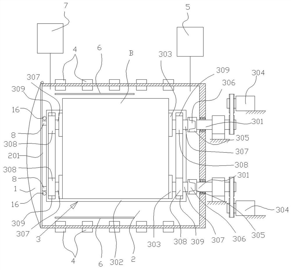
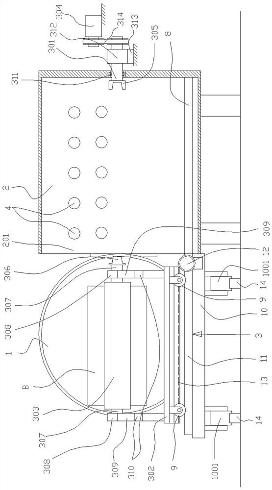
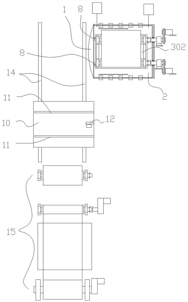
[0022] like figure 1 , 2 As shown, the strip vacuum plasma coating device of the present invention is realized in this way, comprising a circular or oval vacuum coating chamber 2 with a sealed door 1, a winding and unwinding device arranged in the vacuum coating chamber 2 3. The vacuum coating chamber 2 is equipped with a cathode target 4, a vacuum system 5, a heating system 6 and a process gas filling system 7. The special feature is that the winding and unwinding device 3 includes two shafts 301 arranged in the vacuum coating chamber 2. , mobile trolley 302, and rotate side by side the two rolls 303 arranged on the mobile trolley 302, more than one of the two shafts 301 is driven by the power 304 to rotate, and the ends of the two shafts 301 located in the vacuum coating chamber 2 are provided with a female clutch member 305, the end of the winding rol...


PUM


Abstract

The invention discloses a strip vacuum plasma coating method and device. The strip vacuum plasma coating device comprises a vacuum coating chamber and a winding and unwinding device arranged in the vacuum coating chamber. The strip vacuum plasma coating device is characterized in that the winding and unwinding device comprises two shafts arranged in the vacuum coating chamber, a traveling car and two winding rollers rotationally arranged on the traveling car side by side; more than one of the two shafts is driven by power to rotate; female clutch components are arranged at the ends, located in the vacuum coating chamber, of the two shafts; male clutch components are arranged at the ends, opposite to the female clutch components, of the winding rollers; bearings are arranged on the shafts at the two ends of the winding rollers; and bearing supports are arranged on the traveling car corresponding to the bearings of the winding rollers. Compared with the prior art, the method and the device have the advantages that a strip plate can be prevented from being polluted, the stable linear speed during unwinding is ensured, the metal strip plate wound into a roll can be quickly put in, time and labor are saved, and the production efficiency is high.

Description

technical field [0001] The invention relates to a coating technology, in particular to a vacuum plasma coating technology. Background technique [0002] As disclosed in patent CN201720479833.X, the existing strip vacuum plasma coating technology is to install an unwinding device and a winding device in the coating chamber. Put the strip-shaped metal strip on the unwinding device, then put the traction belt of the rolled metal strip on the winding device, and tension the rolled metal strip through the tensioning mechanism on the unwinding device , tension the traction belt through the tensioning mechanism on the winding device, close the coating chamber, evacuate, introduce process gas, start the cathode arc power supply, start the winding device, under the action of the cathode target arc, the cathode target It is sprayed in the form of mist of charged fine water droplets. At this time, since the metal strip is grounded through the winding device and the unwinding device, i...

Claims


Application Information

Patent Timeline
Patent Type & Authority Applications(China)
IPC IPC(8): C23C14/56C23C14/32
CPCC23C14/562C23C14/325
Inventor 杜顺锋
Owner 佛山市天定五金制品有限公司
Learn More