Fabricated dredging mechanism for drainage pipe fitting

An assembly technology for drainage pipe fittings, applied in the field of assembly dredging mechanism for drainage pipe fittings, can solve the problems of drainage system paralysis, lack of automation performance, unfavorable drainage work, etc.

Active Publication Date: 2021-08-03
YUZHOU JIETONG PLASTIC CO LTD
View PDF12 Cites 0 Cited by
  • Summary
  • Abstract
  • Description
  • Claims
  • Application Information

AI Technical Summary

Problems solved by technology

[0003] The existing drainage pipe is a new type of permeable drainage plastic pipe with a corrugated appearance formed by adding other additives to high-density polyethylene. The permeable corrugated pipe is made by punching holes in the groove, and the needle-punched geotextile is outsourced around the pipe. According to the type of bellows, it can be divided into single-wall permeable bellows and double-wall permeable bellows. The orifice is located in the trough. Due to the two-way action of the wave crest and the filter fabric, the orifice is not easy to block, ensuring the smooth flow of the permeable system. When in use, the two ends of multiple drainage pipes are connected to each other, and when transporting sewage or muddy water, etc., some sewage waste or soil will remain in the drainage pipe fittings, and after a long time of drainage, it will cause the drainage pipe fittings In addition, the existing drainage pipes can be dredged to a certain extent when dredging, but the dredging effect is extremely poor, and the internal impurities and soil cannot be thoroughly cleaned. Finally, Existing dredging equipment is unidirectional and does not have automatic performance. Therefore, during the dredging process, it will take a lot of dredging time and waste the strength and time of the staff, which affects the dredging efficiency and is not conducive to drainage work.

Method used


Image

  • Fabricated dredging mechanism for drainage pipe fitting
  • Fabricated dredging mechanism for drainage pipe fitting
  • Fabricated dredging mechanism for drainage pipe fitting

Examples


Embodiment Construction

[0025] The following will clearly and completely describe the technical solutions in the embodiments of the present invention with reference to the accompanying drawings in the embodiments of the present invention. Obviously, the described embodiments are only some, not all, embodiments of the present invention. Based on the embodiments of the present invention, all other embodiments obtained by persons of ordinary skill in the art without making creative efforts belong to the protection scope of the present invention.

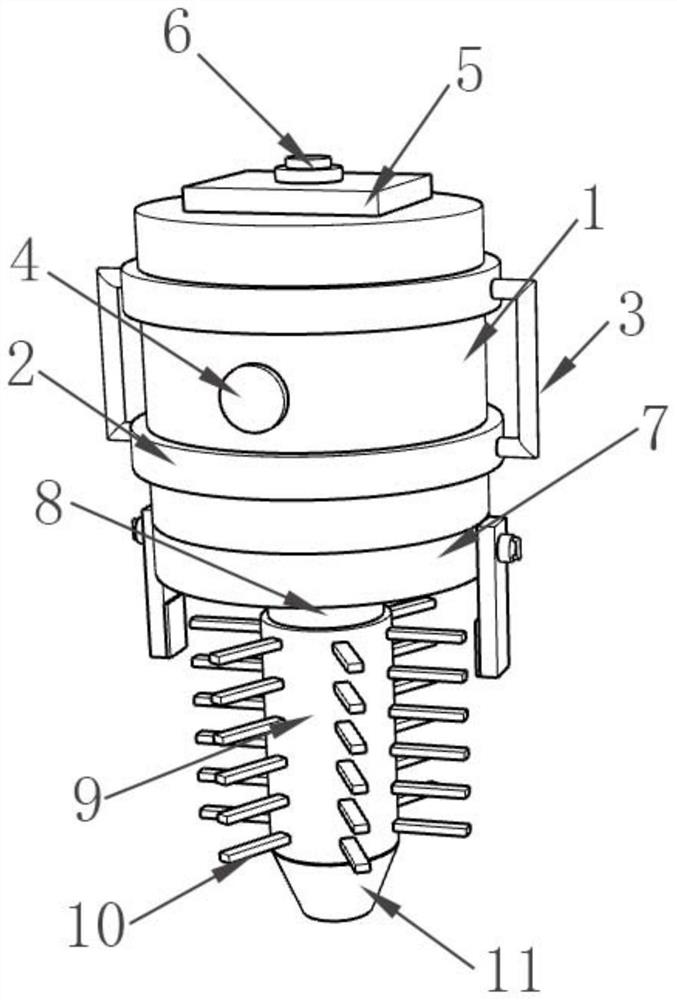
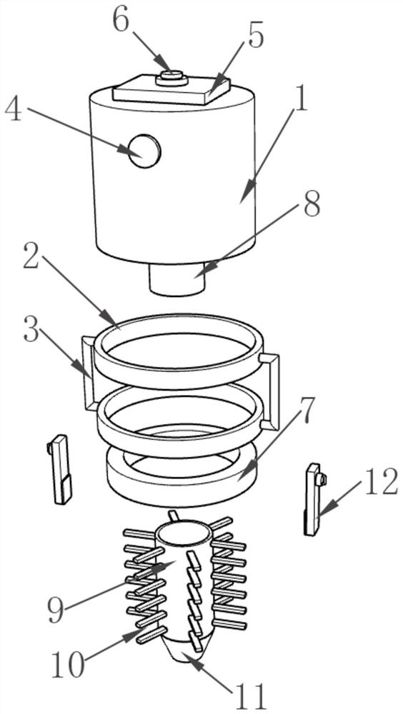
[0026] as attached figure 1 with attached Figure 7 An assembled dredging mechanism for drainage pipe fittings is shown, which includes a dredging barrel body 1, the outer surface of the dredging barrel body 1 is fixedly fitted with a clamping limit frame 2, and the left and right sides of the clamping limit frame 2 Both are fixedly installed with a support handle 3, the outer surface of the dredging barrel body 1 is detachably equipped with a water injection...


PUM


Abstract

The invention discloses a fabricated dredging mechanism for a drainage pipe fitting. The fabricated dredging mechanism for the drainage pipe fitting comprises a dredging barrel body, wherein the outer surface of the dredging barrel body fixedly sleeves with a clamping limiting frame, the left side and the right side of the clamping limiting frame are each fixedly provided with a supporting handle, the outer surface of the dredging barrel body is detachably provided with a water injection cover, and the top of the dredging barrel body is fixedly provided with a first conductive panel; a switch button is fixedly mounted at the top of the first conductive panel, a connecting sleeve fixedly sleeves the bottom of the dredging barrel body, a water guiding pipe fixedly communicates with the bottom of the dredging barrel body, a rotating sleeve fixedly communicates with the bottom of the water guiding pipe, and a cleaning brush fixedly sleeves the outer surface of the rotating sleeve. According to the fabricated dredging mechanism for the drainage pipe fitting, after long-time drainage, the drainage pipe fittings are blocked, so that water flow is blocked, and a drainage system breaks down; at the moment, the drainage pipe fitting can be comprehensively dredged through cooperation of the dredging barrel body, the connecting sleeve, the rotating sleeve and other devices, the dredging efficiency of the drainage pipe fitting is improved, and blockage and breakdown of the drainage system are prevented.

Description

technical field [0001] The invention relates to the technical field of drainage pipe fitting equipment, more specifically, the invention relates to an assembled dredging mechanism for drainage pipe fittings. Background technique [0002] There are many kinds of existing drainage equipment, and their uses are also divided into various types, such as building drainage, domestic drainage and oil well drainage, etc., and in most drainages, drainage pipes are needed, and when the drainage pipes are connected to transport water, Multiple drain fittings are required to interconnect them. [0003] The existing drainage pipe is a new type of permeable drainage plastic pipe with a corrugated appearance formed by adding other additives to high-density polyethylene. The permeable corrugated pipe is made by punching holes in the groove, and the needle-punched geotextile is outsourced around the pipe. According to the type of bellows, it can be divided into single-wall permeable bellows ...

Claims


Application Information

Patent Timeline
Patent Type & Authority Applications(China)
IPC IPC(8): E03F9/00
CPCE03F9/005E03F9/007
Inventor 徐鑫
Owner YUZHOU JIETONG PLASTIC CO LTD
Why Eureka
Try Eureka