Battery protection device, battery assembly and terminal
A battery protection device, battery technology, applied in the direction of battery circuit devices, circuit devices, secondary battery repair/maintenance, etc., can solve the problems of increased charge and discharge circuit impedance, safety issues, and increased influence of charge and discharge circuit temperature rise. The effect of high cost and high precision
- Summary
- Abstract
- Description
- Claims
- Application Information
AI Technical Summary
Problems solved by technology
Method used
Image

Examples
no. 1 example
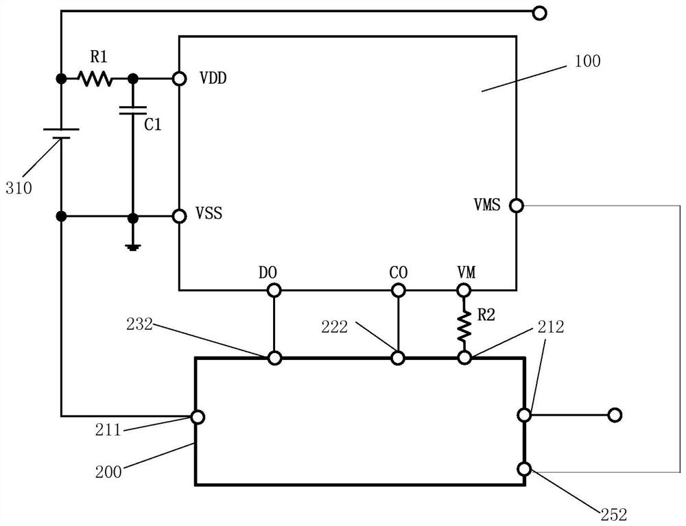
[0099] figure 1 is a schematic diagram of the battery assembly of the first embodiment of the present application, please refer to figure 1 , in this embodiment, the switching tube chip 200 can be used to detect the discharge current of the battery 310 .
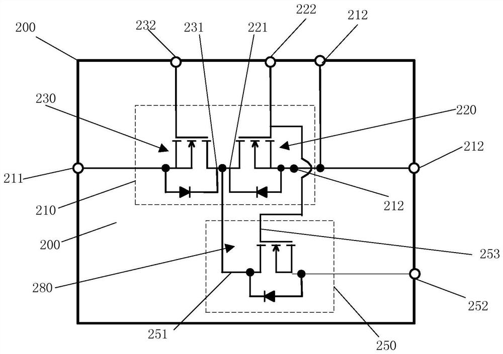
[0100] Specifically, see in conjunction with figure 1 and image 3, in this embodiment, the main switching unit 210 includes a first switching tube group 220 and a second switching tube group 230, of course, in other embodiments of the application, the switching tube groups included in the main switching unit 210 are not limited to two groups , can also include more switching tube groups according to actual needs. In this embodiment, the first switch transistor group 220 includes a plurality of MOS transistors. In this embodiment, the plurality of MOS transistors in the first switch transistor group 220 are connected in parallel, and the second switch transistor group 230 includes a plurality of MOS transistors. In this ...
no. 2 example
[0123] Figure 4 is a schematic diagram of the switch tube chip in the second embodiment of the present application, please refer to Figure 4 , in this embodiment, the switching tube chip 200 can be used to detect the charging current of the battery 310 .
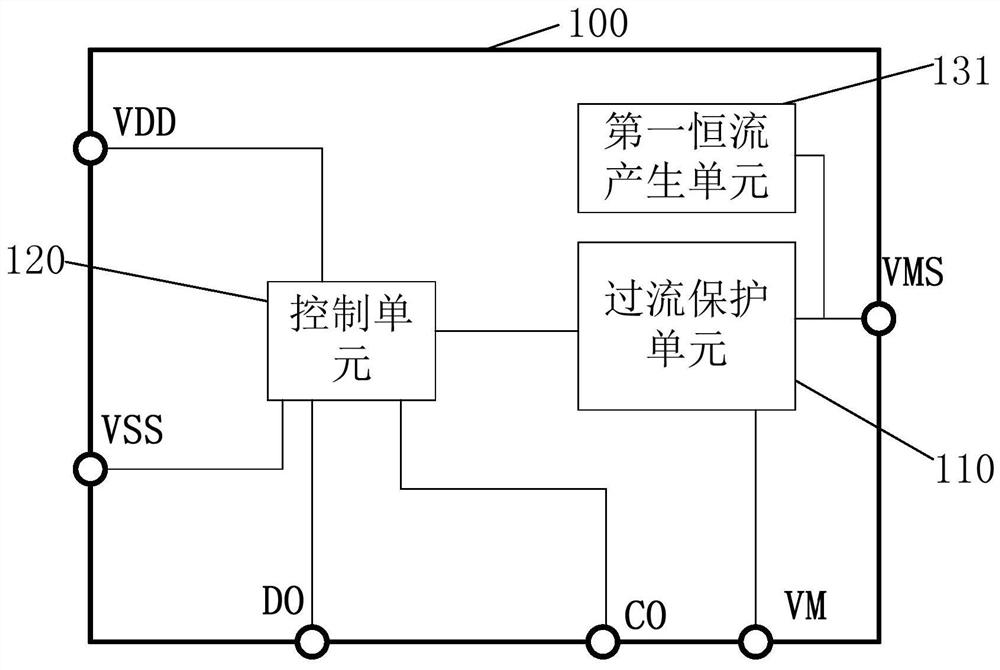
[0124] In this embodiment, like the first embodiment, the main switch unit 210 includes a first switch tube group 220 and a second switch tube group 230, and the switch control terminal of the battery protection module 100 includes a charge control terminal CO and a discharge control terminal DO , the signal of the charging control terminal CO is used to control the first switch tube group 220 to be turned on or off, and the signal of the discharge control terminal DO is used to control the second switch tube group 230 to be turned on or off.
[0125]In this embodiment, the detection switch unit 250 includes a detection switch transistor group 280 , and the connection method of the detection switch transistor group 280 is...
no. 3 example
[0146] Figure 8 is a schematic diagram of the battery assembly of the third embodiment of the present application, please refer to Figure 8-Figure 10 , in this embodiment, the main switch unit 210 and the detection switch unit 250 can be used not only for detecting the discharge current of the battery 310 , but also for detecting the charging current of the battery 310 .
[0147] In this embodiment, like the first embodiment, the main switch unit 210 includes a first switch tube group 220 and a second switch tube group 230, and the switch control terminal of the battery protection module 100 includes a charge control terminal CO and a discharge control terminal DO , the signal of the charging control terminal CO is used to control the first switch tube group 220 to be turned on or off, and the signal of the discharge control terminal DO is used to control the second switch tube group 230 to be turned on or off.
[0148] In this embodiment, the battery protection module 100 ...
PUM
 Abstract
Description
Claims
Application Information
 - R&D
- Intellectual Property
- Life Sciences
- Materials
- Tech Scout
- Unparalleled Data Quality
- Higher Quality Content
- 60% Fewer Hallucinations
Browse by: Latest US Patents, China's latest patents, Technical Efficacy Thesaurus, Application Domain, Technology Topic, Popular Technical Reports.
© 2025 PatSnap. All rights reserved.Legal|Privacy policy|Modern Slavery Act Transparency Statement|Sitemap|About US| Contact US: help@patsnap.com