Magnetic shoe for motor, motor rotor and motor
A motor rotor and magnetic tile technology, applied in the direction of magnetic circuit rotating parts, magnetic circuits, circuits, etc., can solve the problem of large axial magnetic pulling force, and achieve low production cost, improve performance, and reduce axial magnetic pulling force. Effect
- Summary
- Abstract
- Description
- Claims
- Application Information
AI Technical Summary
Problems solved by technology
Method used
Image
Examples
Embodiment 1
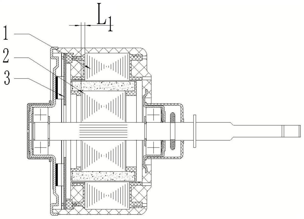
[0051] In this embodiment, a magnetic shoe for a motor is provided, which is used for a permanent magnet motor in which a rotor core and a stator core are offset along the rotor axial direction. The motor includes a motor rotor and a stator, and the magnetic tile includes:
[0052] The excitation part is covered on the outer peripheral surface of the rotor core, and cooperates with the stator air gap to form an excitation circuit;
[0053] The dislocation part is formed on the first end surface of the excitation part, and the dislocation part on the end side protrudes from the end surface of the stator core and the end surface of the rotor core on the same side to form a dislocation arrangement with the stator core and the rotor core, The dislocation part includes: an induction part for being sensed by the rotor position sensing element of the motor; and a magnetic bridge for connecting the induction part and the excitation part to stagger the induction part and the excitation...
Embodiment 2
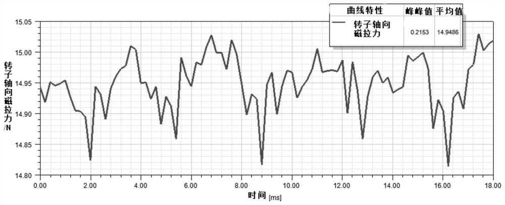
[0063] In this embodiment, a motor rotor is provided, and the motor rotor includes: a rotor; and a plurality of magnetic tiles coated on the outside of the rotor, and any one of the above-mentioned magnetic tiles is used for the magnetic tiles. That is, the rotor is surrounded by any of the above-mentioned "Z", "return" or "I" permanent magnet structures (magnetic tiles) into a circle. It should be noted that the proportion of each magnetic tile is determined according to the actual magnetic pole scheme (that is, the proportion of each magnetic tile is determined according to the actual magnetic pole 8P, 10P... scheme of the motor); this The structure realizes that after the stator and rotor iron cores are misplaced, compared with the existing permanent magnet structure, the axial magnetic pulling force of the permanent magnet structure of the present invention is greatly reduced, and the effect is obvious. In the case that other performances of the motor are not greatly affec...
Embodiment 3
[0065] In this embodiment, a motor is provided, and the motor includes the above-mentioned motor rotor or magnetic tile. Since the stator and rotor of the motor are placed asymmetrically, the permanent magnets of the motor rotor in this embodiment adopt a "Z" type, "back" type or "I" type structure, and the rotor is molded by using multiple pieces of permanent magnets with the same structure. The magnitude of the axial magnetic pull is greatly reduced, which solves the problem that the axial magnetic pull of the motor rotor causes the bearing and wave pad to be stressed for a long time, and the performance and life of the motor are seriously affected.
[0066] The "Z" type, "back" type or "I" type structure adopted by the permanent magnet of the present invention, the asymmetrical part of the permanent magnet relative to the stator core and the outer contour of the excitation part of the air gap all adopt the same three-section arc The structure solves the problem of excessive...
PUM
 Abstract
Description
Claims
Application Information
 - R&D
- Intellectual Property
- Life Sciences
- Materials
- Tech Scout
- Unparalleled Data Quality
- Higher Quality Content
- 60% Fewer Hallucinations
Browse by: Latest US Patents, China's latest patents, Technical Efficacy Thesaurus, Application Domain, Technology Topic, Popular Technical Reports.
© 2025 PatSnap. All rights reserved.Legal|Privacy policy|Modern Slavery Act Transparency Statement|Sitemap|About US| Contact US: help@patsnap.com


