Pushing structure based on computer vision grading equipment

A computer vision and equipment technology, applied in sorting and other directions, can solve the problems of large force on the target object, affecting product quality, single structure and function of pushing material, etc., to achieve the effect of ensuring stability

Inactive Publication Date: 2021-08-06
泉州市晟禄产品设计有限公司
View PDF0 Cites 0 Cited by
  • Summary
  • Abstract
  • Description
  • Claims
  • Application Information

AI Technical Summary

Problems solved by technology

[0003] However, the pushing structure of the existing computer vision grading equipment has a single function and a relatively simple structure. During use, the target object is usually directly pushed, and the target object is subjected to a large force, and the texture is relatively brittle or the fruit and other items are squeezed by a large force. Pressure affects the quality of the product itself

Method used


Image

  • Pushing structure based on computer vision grading equipment
  • Pushing structure based on computer vision grading equipment
  • Pushing structure based on computer vision grading equipment

Examples


Embodiment 1

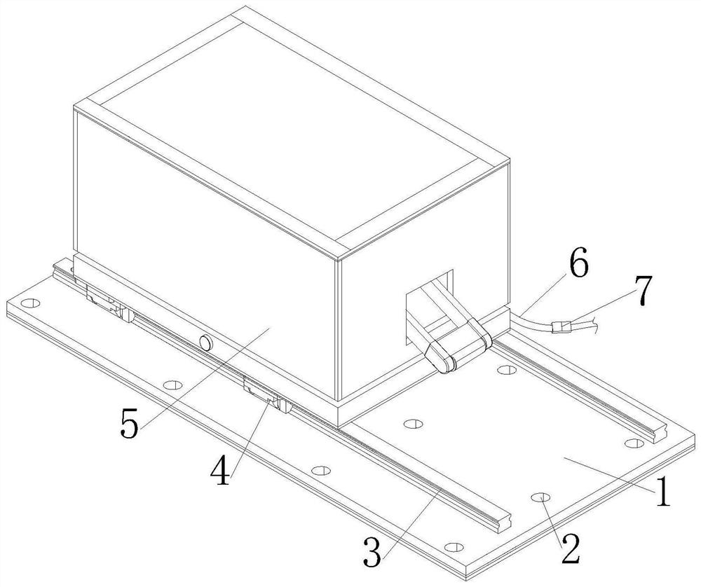
[0034] see figure 1 , a pusher structure based on computer vision grading equipment of the present invention includes a bottom plate 1, a fixing hole 2, a slide bar 3, a slider 4, a top material structure 5, a power cord 6 and a control switch 7, and the surface of the bottom plate 1 is provided with Fixing holes 2, two sliders 3 are fixed on the top of the bottom plate 1, and the top side of the sliders 3 is connected with the slider 4, a power line 6 is arranged on the rear side of the bottom plate 1, and a control switch 7 is installed on the inner side of the power line 6, and the top material The bottom side of the structure 5 is connected with the bottom plate 1, which is convenient for pushing the article and avoids a large thrust on the surface of the article.

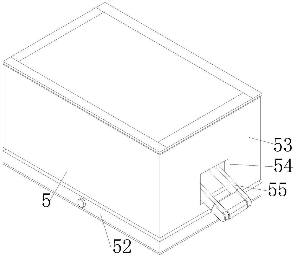
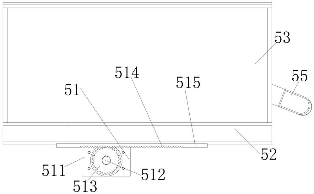
[0035] see figure 2 and image 3, a pusher structure based on computer vision grading equipment of the present invention, the ejector structure 5 includes a displacement assembly 51, a steering assembly 52, ...

Embodiment 2

[0039] In the pusher structure based on computer vision grading equipment of the present invention, the shifting assembly 51 is arranged at the middle side of the bottom of the steering assembly 52, and the front and rear sides of the bottom of the steering assembly 52 are fixed with the slider 4, which is beneficial to the steering assembly. 52 is shifted and supported to ensure stability. The middle side of the top of the rectangular seat 521 is provided with a circular opening, and a bearing ring is embedded inside the circular opening. The inner surface of the bearing ring is in contact with the pole 526 to ensure the rotation of the pole 526. The middle side of the link piece 555 is provided with a bar-shaped groove 5551, and the middle part of the boss 554 runs through the inner side of the bar-shaped groove 5551 to slide and connect with it, and the movement of the boss 554 in the bar-shaped groove 5551 drives the link piece 555 Rotate to ensure the stability of the tran...


PUM


Abstract

The invention discloses a pushing structure based on computer vision grading equipment. The pushing structure comprises a bottom plate, a fixing hole, a sliding strip, a sliding block, a material ejecting structure, a power line and a control switch, and the fixing hole is formed in the surface of the bottom plate. According to the pushing structure, the material ejecting structure is optimally arranged, a small motor is used as a power source, a rectangular seat moves in the horizontal direction through cooperation of a gear and a rack, a worm and a worm gear are installed in the rectangular seat, then a roller can be driven to adjust the position and change the orientation angle in the horizontal direction, meanwhile, a driving motor serves as a power source, one end of the roller is lifted upwards through rotation cooperation of a connecting rod piece and a rod piece, and the roller can slightly move under the action of springs, so that the situation that objects are directly pushed to cause overlarge stress on the objects is avoided, and the quality of the objects during grading is guaranteed to a certain extent.

Description

technical field [0001] The invention relates to the related field of artificial intelligence grading equipment, in particular to a material pushing structure based on computer vision grading equipment. Background technique [0002] In recent years, with the rapid development of image processing technology and computer technology, computer vision technology is used to detect and identify target objects, coupled with transmission machinery to grasp and classify target objects, whether in industrial or agricultural fields, It is getting more and more in-depth research and multi-directional application promotion; when computer vision grading equipment is used, it usually uses the push structure to push and collect the detected objects. [0003] However, the pushing structure of the existing computer vision grading equipment has a single function and a relatively simple structure. During use, the target object is usually directly pushed, and the target object is subjected to a la...

Claims


Application Information

Patent Timeline
Patent Type & Authority Applications(China)
IPC IPC(8): B07C5/342B07C5/02
CPCB07C5/02B07C5/3422
Inventor 陈旭波
Owner 泉州市晟禄产品设计有限公司
Why Eureka
Try Eureka