

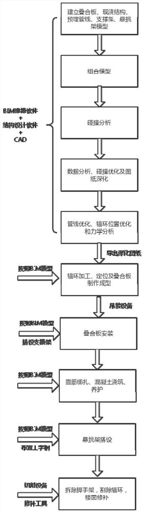
Laminated slab cantilever I-shaped steel construction method based on BIM (Building Information Modeling) technology
A construction method and technology of laminated slabs, which are applied to floor slabs, accessories of scaffolding, scaffolding supported by house structures, etc., can solve the problems of complex steel reinforcement system, failure of normal installation of anchor rings, hidden dangers of structural safety, etc., and reduce the cost of post-opening holes. and plugging costs, improve efficiency and molding quality, and reduce structural safety hazards.
- Summary
- Abstract
- Description
- Claims
- Application Information
AI Technical Summary
Problems solved by technology
Method used
Image

Examples
Embodiment Construction
[0042] In order to make the purpose, technical solutions and advantages of the embodiments of the present invention clearer, the technical solutions in the embodiments of the present invention will be clearly and completely described below in conjunction with the embodiments of the present invention. Obviously, the described embodiments are part of the implementation of the present invention. way, but not all implementations. Based on the implementation manners in the present invention, all other implementation manners obtained by persons of ordinary skill in the art without making creative efforts belong to the scope of protection of the present invention. Accordingly, the detailed description of the embodiments of the invention provided below is not intended to limit the scope of the claimed invention but is merely representative of selected embodiments of the invention.
[0043] In the description of the present invention, it should be understood that the terms indicating o...
PUM
 Abstract
Description
Claims
Application Information