
Clamping and hoisting device

A hoisting plate and hoisting hole technology, used in auxiliary devices, auxiliary welding equipment, welding/cutting auxiliary equipment, etc., can solve the problem that the torsional buckling deformation of box-shaped components is difficult to control, the levelness and verticality of box-shaped components cannot reach, Constraining the smooth implementation of construction progress and quality, and achieving the effects of safe construction, social and economic benefits, convenient and fast construction operations, and reduction of hidden structural safety problems

Pending Publication Date: 2020-09-18
JINCHUAN GROUP LIMITED
View PDF0 Cites 0 Cited by
  • Summary
  • Abstract
  • Description
  • Claims
  • Application Information

AI Technical Summary

Problems solved by technology

[0003] In the prior art, box-shaped components are manufactured by combining electroslag welding and submerged arc welding to weld the web and flange plates. During the welding construction, welding deformation will occur due to the distribution of welding stress. The torsional buckling is easy to occur during welding construction; the torsional buckling deformation of box-shaped members is difficult to control. At present, there is no special correction equipment for the deformation of box-shaped members, resulting in the horizontality and verticality of box-shaped members. requirements, rework processing causes material loss and waste, increases construction costs, causes over-burning phenomena due to excessive welding, various welding defects and the possibility of increased stress concentration, causing hidden dangers to structural safety, reducing structural safety reserves, and seriously restricting construction progress. smooth implementation of quality

Method used


Image

  • Clamping and hoisting device
  • Clamping and hoisting device
  • Clamping and hoisting device

Examples


Embodiment Construction

[0018] The present invention will be described in detail below in conjunction with the accompanying drawings and specific embodiments.

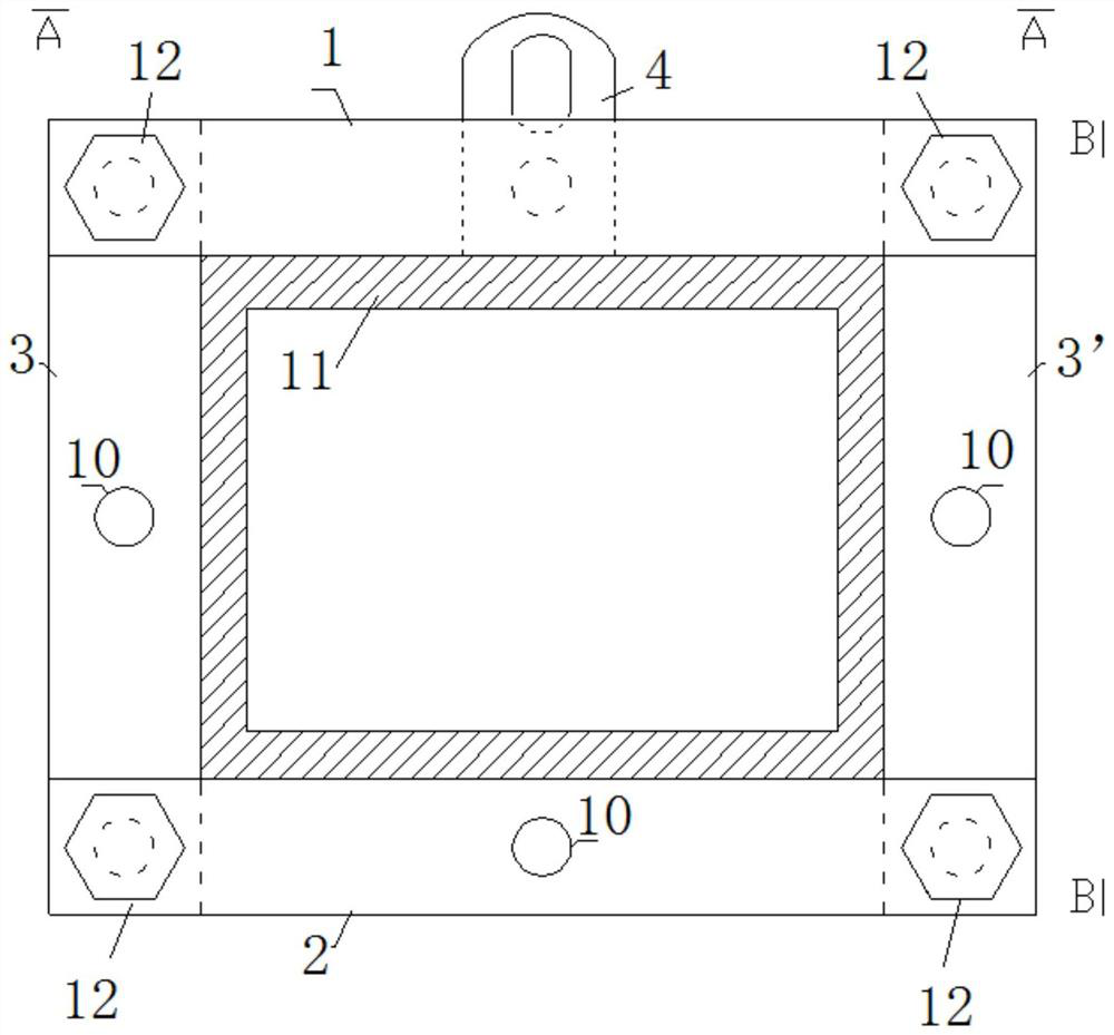
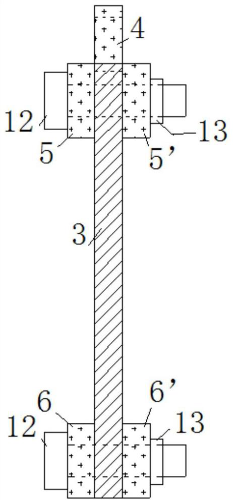
[0019] Such as Figure 1-4 As shown, a clamping and hanging device includes: an upper splint 1, a lower splint 2, two vertical splints 3, 3 ', and a lifting plate 4;

[0020] The upper clamping plate 1 has the same structure as the lower clamping plate 2. The upper clamping plate 1 comprises two horizontal rectangular plates 5, 5' arranged oppositely, and the lower clamping plate 2 comprises two horizontal rectangular plates 6, 6' arranged oppositely (such as image 3 As shown), the two ends of the upper splint 1 and the lower splint 2 are provided with corresponding bolt holes;

[0021] The two vertical splints are rectangular plates arranged vertically, the upper end of the vertical splint 3 is connected to one end of the upper splint 1, the lower end of the vertical splint 3 is connected to one end of the lower splint 2, and the upper end...


PUM


Abstract

The invention discloses a clamping and hoisting device. The clamping and hoisting device comprises an upper clamping plate, a lower clamping plate, two vertical clamping plates and a hoisting plate; the upper clamping plate and the lower clamping plate are the same in structure, and each of the upper clamping plate and the lower clamping plate comprise two oppositely-arranged horizontal plates; the upper ends of the vertical clamping plates are connected with one end of the upper clamping plate, and the lower ends of the vertical clamping plates are connected with one end of the lower clampingplate; and first connecting holes are formed in the middles of the upper clamping plate, the lower clamping plate and the two vertical clamping plates, and the hoisting plate is connected with the first connecting holes. The clamping and hoisting device has the advantages that processing manufacturing is simple, construction operation is convenient and quick, safety and stability are achieved, repeated disassembly and assembly for use is achieved, initial damage of rework treatment to the components is avoided, cost is low, construction cost is reduced, and construction efficiency is improved.

Description

technical field [0001] The invention belongs to the field of construction equipment, and in particular relates to a clamping and hanging device. Background technique [0002] Due to its mechanical characteristics (high rigidity) and process equipment layout requirements, box-shaped members are often used in frame structures; box-shaped members are formed by welding two webs and two flanges. [0003] In the prior art, box-shaped components are manufactured by combining electroslag welding and submerged arc welding to weld the web and flange plates. During the welding construction, welding deformation will occur due to the distribution of welding stress. The torsional buckling is easy to occur during welding construction; the torsional buckling deformation of box-shaped members is difficult to control. At present, there is no special correction equipment for the deformation of box-shaped members, resulting in the horizontality and verticality of box-shaped members. requiremen...

Claims


Application Information

Patent Timeline
Patent Type & Authority Applications(China)
IPC IPC(8): B23K37/00B23K37/047
CPCB23K37/00B23K37/047
Inventor 李卫向
Owner JINCHUAN GROUP LIMITED
Learn More