Battery fixing and locking device and locking method

A battery fixing and locking device technology, which is applied to battery pack parts, circuits, building locks, etc., can solve the problems of lock battery damage, lock cylinder falling off, battery pack wear, etc.

Pending Publication Date: 2021-08-06
郑州锐晶裕华新能源有限公司
View PDF6 Cites 0 Cited by
  • Summary
  • Abstract
  • Description
  • Claims
  • Application Information

AI Technical Summary

Problems solved by technology

[0002] At present, the detachable batteries are all fixed by external locks or internal locking mechanisms, but the external locks are not aesthetically pleasing when used, and the external locks are easy to shake, causing wear and tear on the battery pack; the internal locking mechanism is the lock core. Cooperating with the locking mechanism, the locking mechanism is maintained by the lock cylinder to complete the fixing of the battery pack. However, the existing internal locking mechanism operates through the lock cylinder to enter the limit position, and it is necessary to lock the lock on the battery with force. On the warehouse, this will cause a great risk of damage to the lock and its battery. At the same time, due to the harsh application environment of some battery packs, in the case of frequent vibrations, it is easy to cause the lock cylinder to fall off, resulting in the failure of the limit hold operation. At the same time, when dust and other sundries enter the inside of the lock cylinder, it is easy to get stuck inside the lock cylinder, making it difficult to insert the key, resulting in difficulty or failure in unlocking or locking.

Method used


Image

  • Battery fixing and locking device and locking method
  • Battery fixing and locking device and locking method
  • Battery fixing and locking device and locking method

Examples


Embodiment

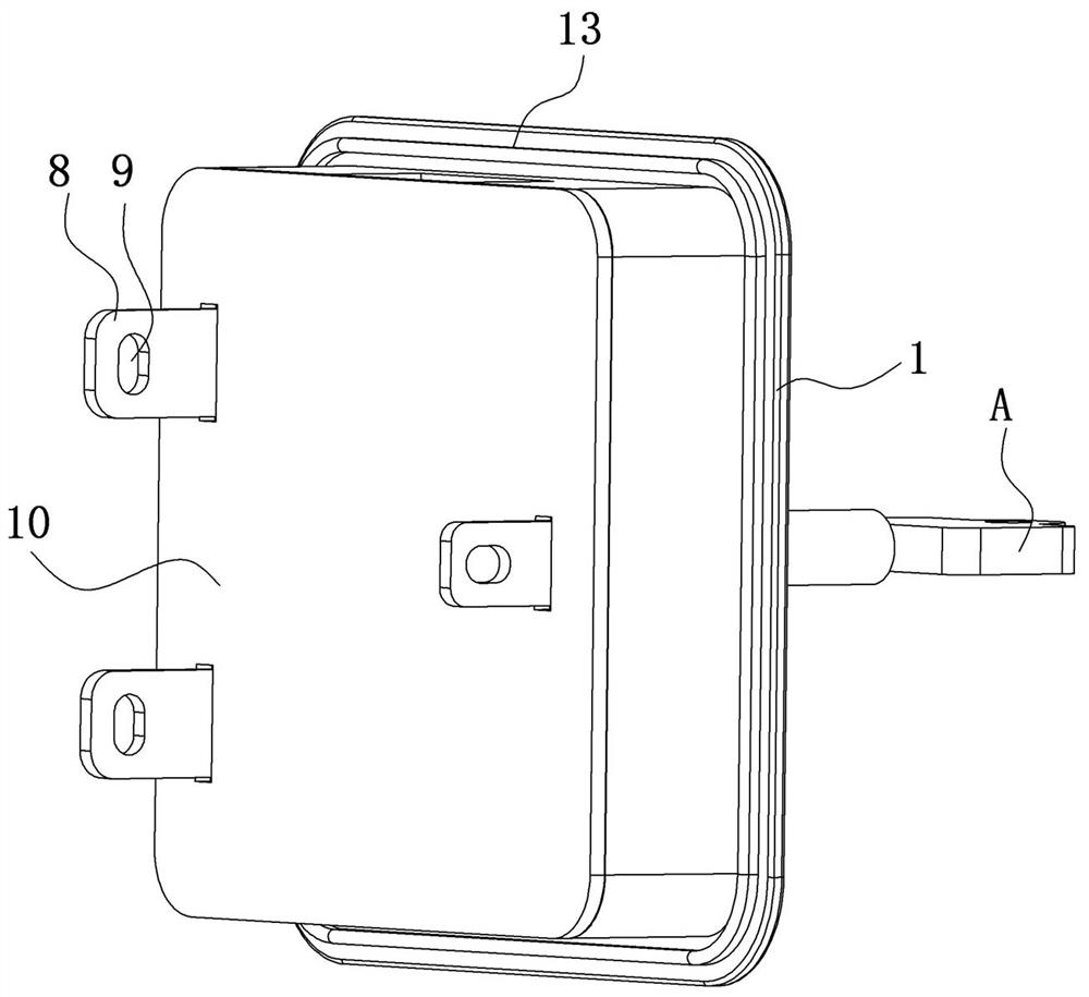
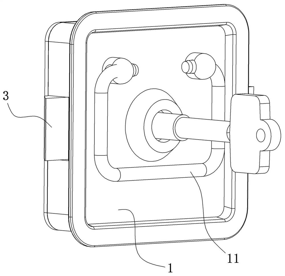
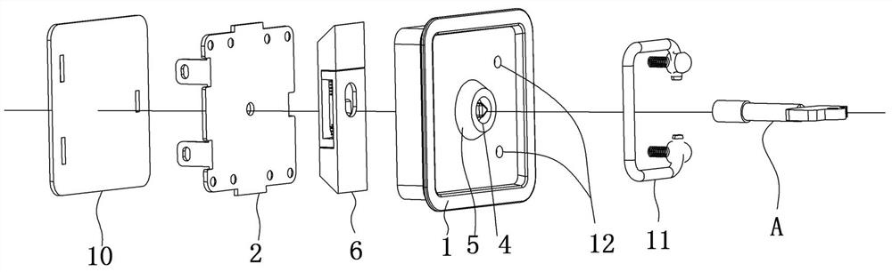
[0036] Example: See figure 1 , figure 2 , image 3 , Figure 4 , Figure 5 and Image 6 , Figure, 1-lock seat, 2-lock fixing plate, 3-guide groove, 4-rotary shaft, 5-keyhole, 6-lock module, 7-positioning hole, 8-mounting plate, 9- Mounting hole, 10-anti-rush pad, 11-handle, 12-screw hole, 13-rubber ring;

[0037] 61-lock tongue, 62-limit plate, 63-spring, 64-U tank, 65-linkage hole, 66-runway hole, 67-guide hole, 68-guide column; A-key.

[0038]A battery fixed locking device and a locking method including a lock cover, a lock tongue module, and a rotating shaft, and the lock cover comprises a lock seat and a lock fixing plate having a chamber, and the lock holder. A guiding groove is provided on both sides, the rotating shaft is rotated through the through hole in the lock seat, and one end of the rotating shaft is placed in the keyhole in communication with the outside, and the other end of the rotating shaft extension In the chamber, the lock tongue module provided in the guide groo...

Embodiment 1

[0041] The lock cover includes a locking seat 1 and a locking plate 2 having a chamber to form a chamber, and any one of the opposite sides of the lock seat 1 is provided with a guide groove 3, and the rotating shaft 4 is provided on the lock seat 1. The through hole rotation is penetrated on the lock seat 1, and one end of the rotating shaft 4 is placed in the keyhole 5 in communication with the outside, and the other end of the rotating shaft 4 extends into the chamber, and is a lock module disposed within the guide groove 3. 6 linkage, and drive the lock tongue module 6 to move along the guide groove 3;

[0042] The lock seat 1 and the locking plate 2 are lid each other to form a chamber, and any of the opposite sides of the lock seat 1 is provided with a guide groove 3 in communication with the chamber and the outside, and the lock tongue module 6 is placed in the guide groove 3. The lock tongue module 6 is limited to the line movement.

[0043] The rotating shaft 4 rotates th...

Embodiment 2

[0051] In this example, the other technical features are added to the present embodiment, and the remaining technical features are the same as those of the embodiment, and the same is not described herein, where the increased technical features are increasing. : The lock holder 2 is overped with a rectangular hole 10, and thereon is provided with a rectangular aperture through which the mounting plate 8 is provided, and a rubber ring 13 is disposed around the lock seat 1; a screw hole 12 is provided on the lock seat 1. And connect by rotating the screw with the handle 11.

[0052] The lock seat 1 is provided with a screw hole 12, and is connected by the rotating screw and the handle 11, which is easy to take the lock seat 1 by handle 11, and the locking plate 2 has a reaction pad 10, when the lock When the head seat 1 is mounted from the battery, the head is mounted with the battery, and the locking seat is provided with a rubber ring 13 around the lock seat 1, which acts as a sho...


PUM


Abstract

The invention discloses a battery fixing and locking device and a locking method. The battery fixing and locking device comprises a lock head cover, a spring bolt module and a rotating shaft; the lock head cover comprises a lock head seat and a lock head fixing plate, guide grooves are formed in any two opposite sides of the lock head seat, the rotating shaft rotationally penetrates through the lock head seat, one end of the rotating shaft is arranged in a key hole, the other end of the rotating shaft extends into a cavity to be linked with the spring bolt module arranged in the guide grooves and drives the spring bolt module to do reciprocating rectilinear motion along the guide grooves. According to the battery fixing and locking device, through cooperation of the lock head cover, the spring bolt module and the rotating shaft, the spring bolt module stretches out of and stretches into the lock head cover, the lock head cover is in the locked and unlocked states, meanwhile, in cooperation with a locking structure formed by a limiting plate and a spring, the locked and unlocked states of the lock head cover are limited and kept, locking and unlocking operation is convenient, a battery can be conveniently and reliably inserted into a battery bin only by inserting a key and rotating the key, and the risk that the locking device and the battery are damaged cannot be generated.

Description

Technical field [0001] The present invention relates to a battery fixed locking device and a locking method belonging to the technical field of battery. Background technique [0002] At present, detachable batteries are fixed by an external lock or internal locking mechanism, but the plug-in is not good at the time of use, and the outer lock is easy to shake, resulting in the wear of the battery pack; the internal locking mechanism is the lock core. With the mating of the locking mechanism, the locking mechanism is maintained by the lock core, and the fixation of the battery pack is completed. However, the existing internal locking mechanism holds the operation by the lock core, and it is necessary to lock the lock in the battery. On the warehouse, this will cause great damage to the lock and its batteries. At the same time, because some battery pack applications are poor, in the case of frequent vibration, it is easy to cause the lock core to fall off, resulting in failure of li...

Claims


Application Information

Patent Timeline
Patent Type & Authority Applications(China)
IPC IPC(8): E05B15/00E05B15/10E05B63/14E05B65/00H01M50/264
CPCE05B15/00E05B15/101E05B63/146E05B65/00
Inventor 张爱武袁子茹
Owner 郑州锐晶裕华新能源有限公司
Why Eureka
Try Eureka