
High-pressure-resistant soluble bridge plug

A technology of high pressure resistance and bridge plug, which is applied in wellbore/well components, earthwork drilling, sealing/isolation, etc. It can solve the problems that it is difficult to meet the performance requirements of bridge plugs, and avoid poor anchoring and glue damage to the cylinder and improve reliability

Active Publication Date: 2021-08-06
DAQING SHENGWEI MACHINERY MFG
View PDF13 Cites 1 Cited by
  • Summary
  • Abstract
  • Description
  • Claims
  • Application Information

AI Technical Summary

Problems solved by technology

With the continuous application of new technology, the requirements for the pressure bearing capacity of the rubber cylinder in the bridge plug and the anchoring reliability of the slips are getting higher and higher. It is difficult for the traditional bridge plug to meet the performance requirements of the new technology for the bridge plug.

Method used


Image

  • High-pressure-resistant soluble bridge plug
  • High-pressure-resistant soluble bridge plug
  • High-pressure-resistant soluble bridge plug

Examples


Embodiment 1

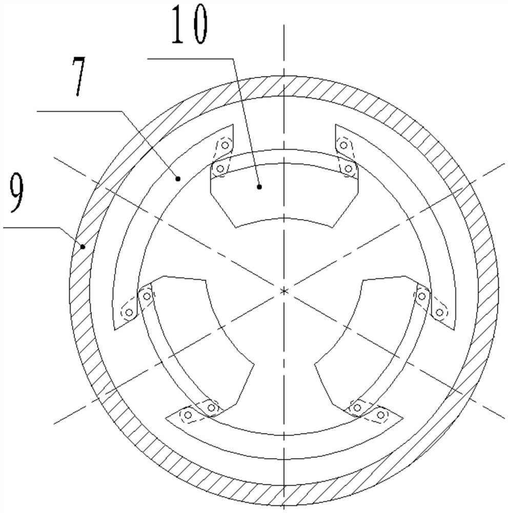
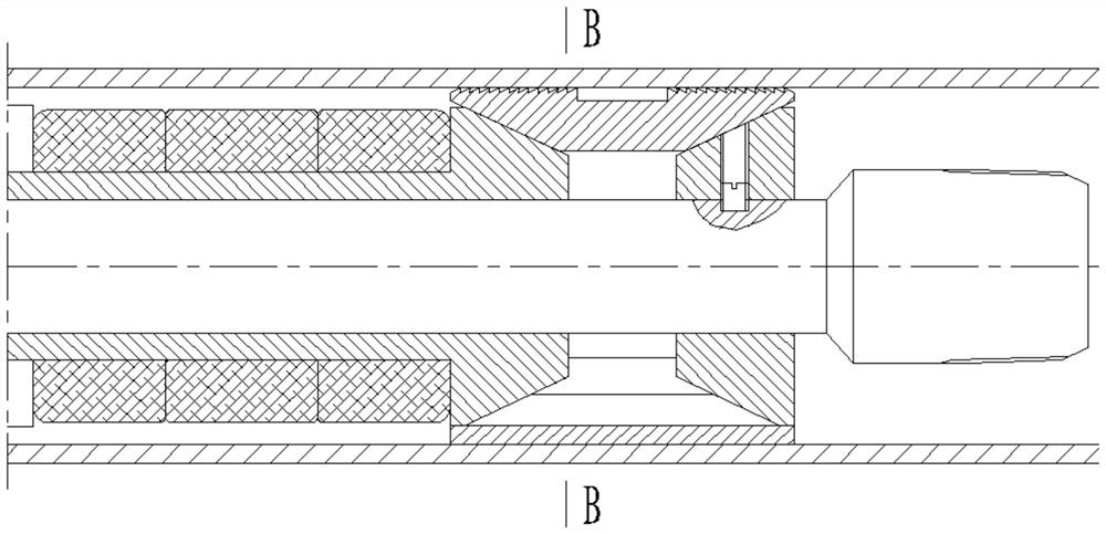
[0034] Such as figure 1 As shown, the present invention includes an upper joint 1 , a central pipe 2 , a rubber cartridge 5 , an upper cone 6 , a lower cone 8 and slips 10 . The above structure is a common structure in the prior art, and will not be repeated here.

[0035] Such as figure 1 As shown, the upper joint 1 is screwed to the upper end of the central tube 2, the upper cone 6 is slidably installed on the central tube 2, the lower cone 8 is fixedly installed on the central tube 2, and the rubber tube 5 is set on the upper cone 6, the upper cone 6 is also equipped with a setting piston 4 and a piston sleeve 3, the side wall of the upper cone 6 is equipped with a lock block 12 that can slide in the radial direction, and the inner wall of the setting piston 4 is connected with the lock block 12 is correspondingly provided with a locking groove, and one end of the slider is inserted into the locking groove, thereby locking the setting piston 4 on the upper cone 6; the out...

Embodiment 2

[0047] The difference between this embodiment and Embodiment 1 is that the locking method of the upper cone 6 has been improved, and the specific improvement methods have the following two points:

[0048] 1. A slip ring 17 is added on the upper cone 6, and a shoulder 18 matching the outer edge of the slip ring 17 is processed on the inner side of the slip 10.

[0049] 2. Between the upper joint 1 and the piston sleeve 3, a C-shaped circlip 13 and a one-way stop thread 11 cooperating with the C-shaped circlip 13 are added.

[0050] In the first embodiment, the setting of the first stage depends on the locking of the locking block 12 after the second stage is started, which requires high machining accuracy of the parts and poor adaptability to well pipes 9 of different diameters.

[0051] In this example, in Figure 7 In the state shown, the upper cone 6 can still be further wedged between the central tube 2 and the slip 10, and at the same time, the axial relative position of...

Embodiment 3

[0053] The difference between this embodiment and Embodiment 1 is:

[0054] Such as Figure 8 As shown, a mandrel 20 is installed on the inner side of the central tube 2, and a torsion spring 21 is arranged between the mandrel 20 and the inner wall of the mounting hole where it is located; All are connected with soft rope 19, and central tube 2 side walls are provided with through holes for passing through soft rope 19, and torsion spring 21 is in the state of accumulating energy all the time (that is at least a part of soft rope 19 is always pressed by the elastic force of torsion spring 21 traction); the length of the soft rope 19 between the slips 10 and the mandrel 20 is equal to the maximum distance between the slips 10 and the mandrel 20; the length of the soft rope 19 between the arc plate 7 and the mandrel 20 is longer than that of the arc plate The maximum distance between 7 and the mandrel 20 is large, and the difference is equal to the thickness of the arc plate 7 ...


PUM


Abstract

A high-pressure-resistant soluble bridge plug relates to the technical field of downhole tools and comprises an upper connector, a central tube, a rubber sleeve, an upper cone, a lower cone and slips, the upper connector is connected to the upper end of the central tube through threads, the upper cone is slidably mounted on the central tube, the lower cone is fixedly mounted on the central tube, the rubber sleeve is sleeved on the upper cone, and the slips are sleeved on the lower cone. A setting piston and a piston sleeve are further installed on the upper cone, a locking block capable of sliding in the radial direction is installed on the side wall of the upper cone, a locking groove corresponding to the locking block is formed in the inner wall of the setting piston, and one end of the sliding block is inserted into the locking groove. The arc-shaped plates are arranged, after setting, the upper end faces of the three arc-shaped plates and the upper end faces of the three slips are jointly spliced into a complete circular ring face, after setting of the rubber barrel, the circular ring face can block the lower side of the rubber barrel, the outer edge of the rubber barrel is prevented from moving downwards after bearing pressure, and according to the sealing principle, the rubber barrel is prevented from moving downwards. The measure can greatly improve the sealing performance of the rubber sleeve when the rubber sleeve bears high pressure, so that the pressure bearing capacity of the rubber sleeve is greatly improved.

Description

technical field [0001] The invention belongs to the technical field of downhole tools, in particular to a high-pressure-resistant soluble bridge plug. Background technique [0002] The bridge plug is a downhole tool commonly used in oilfield production. When the bridge plug is installed in a certain position downhole, the well pipe can be blocked, thereby creating conditions for downhole construction. The structure of the bridge plug includes a rubber tube and slips. After the bridge plug is installed, the rubber tube and the slips are set through the corresponding mechanism. Among them, the rubber tube is compressed after setting, and the outer diameter increases after compression and fits together. On the inner wall of the well pipe, it acts as a seal. After setting, the slips move away from the centerline of the bridge plug, and finally anchor on the inner wall of the well pipe, thereby preventing the bridge plug from moving in the well pipe. With the continuous applicat...

Claims


Application Information

Patent Timeline
IPC IPC(8): E21B33/134E21B33/129
CPCE21B33/129E21B33/134
Inventor 席赫
Owner DAQING SHENGWEI MACHINERY MFG
Learn More