Method and system for modifying Pod network interface during operation based on CNI plug-in in K8s

A network interface and network technology, applied in the field of modifying the Pod network interface, can solve the problems that the Pod’s network interface cannot be modified, cannot meet such requirements, and cannot dynamically access data sources, etc., so as to improve the overall performance and reliability, and apply Strong performance and high fault tolerance

Active Publication Date: 2021-08-06
SHANGHAI NETIS TECH
8 Cites 1 Cited by

AI-Extracted Technical Summary

Problems solved by technology

[0006] In view of the prior art mentioned above, the inventor believes that it is impossible to dynamically access different data sources or send them to different destinations on demand (such as external instructions) during the running of the Pod, and ...

Method used

Based on the K8s Operator programming model, the K8s Operator programming model refers to continuously monitoring the state of certain resources in the K8s cluster in the form of a program, and performing corresponding processing without manual intervention throughout the process, which is a k...

Abstract

The invention provides a method and a system for modifying a Pod network during operation based on a CNI plug-in in K8s. The method comprises the following steps: Pod is called to nodes; the Kubelet is used for calling a Multi CNI (Computer Network Interface) cmdAdd interface; the Multi CNI calls a Dturbo CNI cmdAdd interface, and the Dturbo CNI cmdAdd interface is called by the Multi CNI; the Dturbo CNI generates a Pod network namespace record in the cmdAdd interface; when the Operator monitors the newly added Pod network namespace record, the Operator creates a corresponding network interface according to the Pod network interface definition; the Pod is removed from the node; the Kubelet is used for calling a Multi CNI (Computer Network Interface) cmdDel interface; the Multi CNI calls a Dturbo CNI cmdDel interface, and the Dturbo CNI cmdDel interface is called by the Multi CNI; the Dturbo CNI deletes a Pod network namespace record in the cmdDel interface; when the Operator monitors that the network namespace record is deleted, the Operator deletes the existing network interface of the Pod; a Pod network interface definition is externally modified; the Operator monitors that the definition of the network interface in the Pod configuration is modified; the Operator deletes the existing network interface of the Pod; and the Operator creates a corresponding network interface according to the modified Pod network interface definition. According to the invention, the capability of modifying the Pod network interface during operation is provided, and specific service requirements are met.

Application Domain

Program loading/initiatingSoftware simulation/interpretation/emulation

Technology Topic

Plug-inReal-time computing +5

Image

  • Method and system for modifying Pod network interface during operation based on CNI plug-in in K8s
  • Method and system for modifying Pod network interface during operation based on CNI plug-in in K8s
  • Method and system for modifying Pod network interface during operation based on CNI plug-in in K8s

Examples

  • Experimental program(1)

Example Embodiment

[0083] The present invention will be described in detail below with reference to specific embodiments. The following examples will help those skilled in the art to further understand the present invention, but do not limit the present invention in any form. It should be noted that, for those skilled in the art, several changes and improvements can be made without departing from the inventive concept. These all belong to the protection scope of the present invention.
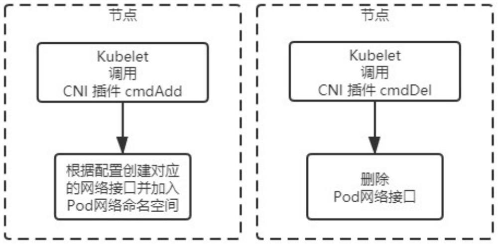
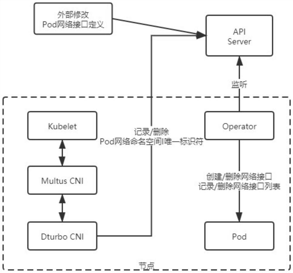
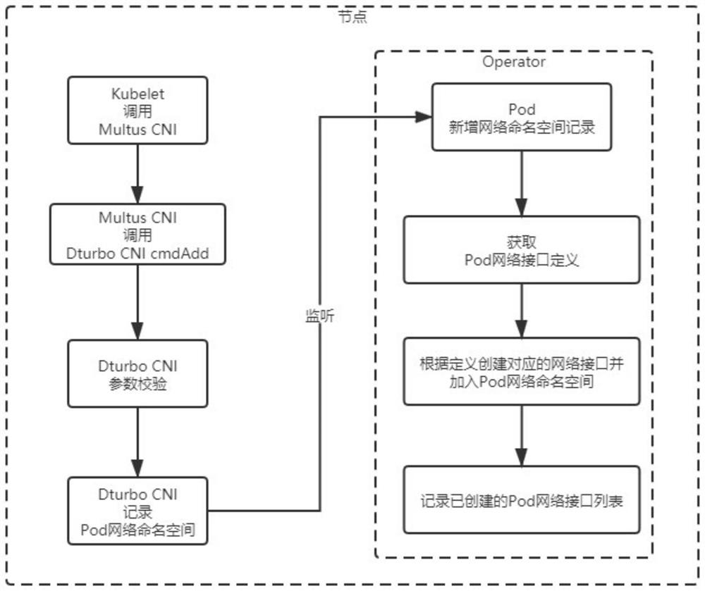
[0084] The embodiment of the present invention discloses a method and system for modifying a Pod network at runtime based on a CNI plug-in in K8s, such as figure 2 As shown, this system includes the following components: A node is a node in a K8s cluster, and its function is to run a physical machine or a virtual machine of the Pod. The API server is the K8s cluster API server, and the function of the API server is the cluster control center.
[0085] Among them, the node includes the following components: Kubelet is the management software on the node, and its function is to realize the functions of all control planes on the node. Multus CNI is a Pod network plugin whose role is to manage multiple sub-network plugins. Dturbo CNI is also a Pod network plugin, its role is to generate or delete Pod network namespace records. Operator is a monitoring container. Its function is to monitor changes in Pod network interface definition and Pod network namespace record changes, and configure the Pod's network interface. Pods are application containers whose role is to run specific services, such as packet playback or packet processing.
[0086] Based on the K8s Operator programming model, the K8s Operator programming model refers to continuously monitoring the status of certain resources in the K8s cluster in a programmatic way and performing corresponding processing without manual intervention in the whole process. It is a robust and fault-tolerant intelligence. Operation and maintenance methods. Operators are deployed on each node and are only responsible for monitoring Pods on this node. The network interface configuration is localized, which improves overall performance and reliability.
[0087] The method includes the following steps: image 3 As shown, Pod network creation steps: This step includes the following steps: Creation step 1: Pod creation, scheduling Pods to nodes. Creation Step 2: The Kubelet calls the Multus CNI cmdAdd interface. Creation Step 3: Multus CNI calls Dturbo CNI cmdAdd interface.
[0088] Creation Step 4: Dturbo CNI generates a Pod network namespace record in the cmdAdd interface and records it into the Pod configuration. Step 4 of creation includes the following steps: Step 4.1 of creation: Dturbo CNI performs parameter verification in the cmdAdd interface. Creation Step 4.2: Dturbo CNI records the unique identifier of the Pod network namespace allocated by the container (container such as docker) at runtime in the cmdAdd interface into the Pod configuration, and generates a Pod network namespace record. The Pod network namespace is a mechanism provided by the Linux operating system to isolate the container network.
[0089] Creation Step 5: The Operator monitors the newly added Pod network namespace record in the Pod configuration, and the Operator creates the corresponding network interface according to the obtained Pod network interface definition. Creation step 5 includes the following steps: Creation step 5.1: The operator listens to the new Pod network namespace record in the Pod configuration from the API Server. Creation Step 5.2: The Operator obtains the Pod network interface definition from the API Server. Creation step 5.3: The operator creates the corresponding network interface according to the Pod network interface definition and adds it to the Pod network namespace. Creation Step 5.4: The Operator records the created Pod network interface into the Pod configuration and generates a list of Pod network interfaces.
[0090] like Figure 4 As shown, the Pod network destruction steps include the following steps: Destruction Step 1: Pod destruction, delete the Pod from the node. Destruction step 2: The Kubelet calls the Multus CNI cmdDel interface. Destruction step 3: Multus CNI calls the DturboCNI cmdDel interface.
[0091] Destruction Step 4: Dturbo CNI deletes the Pod network namespace record from the Pod configuration in the cmdDel interface. Destruction step 4 includes the following steps: Destruction step 4.1: Dturbo CNI performs parameter verification in the cmdDel interface. Destruction Step 4.2: Dturbo CNI deletes the Pod network namespace record from the Pod configuration in the cmdDel interface.
[0092] Destruction Step 5: The Operator listens to the deletion of the network namespace record in the Pod configuration, and the Operator deletes the existing network interface of the Pod. Destruction step 5 includes the following steps: Destruction step 5.1: The operator monitors from the API Server that the network namespace record in the Pod configuration is deleted. Destruction Step 5.2: The Operator obtains a list of Pod network interfaces. Destruction step 5.3: The operator deletes the corresponding network interface according to the Pod network interface list. Destruction Step 5.4: The Operator removes the list of Pod network interfaces from the Pod configuration.
[0093] like Figure 5 As shown, the Pod network modification steps include the following steps: Modification step 1: External (operation and maintenance personnel or programs) modify the definition of the Pod network interface. Modification step 2: The Operator monitors that the network interface definition in the Pod configuration is modified, the Operator deletes the existing network interface of the Pod, and the Operator creates the corresponding network interface according to the modified Pod network interface definition. Modifying step 2 includes the following steps: Modifying step 2.1: The operator monitors that the network interface definition in the Pod configuration is modified. Modify step 2.2: Operator obtains a list of Pod network interfaces. Modify step 2.3: The operator deletes the existing network interface of the corresponding Pod according to the Pod network interface list. Modify step 2.4: The operator removes the list of pod network interfaces from the pod configuration. Modification step 2.5: The operator obtains the modified Pod network interface definition. Modify step 2.6: The operator creates the corresponding network interface according to the Pod network interface definition and adds it to the Pod network namespace. Modify step 2.7: The operator records the created Pod network interface into the Pod configuration, and generates a list of Pod network named interfaces.
[0094] The configuration is based on the existing Network Attachment Definition (Network Attachment Definition) of the K8s community (The Network Plumbing Working Group), with strong compatibility and applicability.
[0095]Those skilled in the art know that, in addition to implementing the system provided by the present invention and its various devices, modules and units in the form of purely computer-readable program codes, the system provided by the present invention and its various devices can be implemented by logically programming the method steps. , modules, and units realize the same function in the form of logic gates, switches, application-specific integrated circuits, programmable logic controllers, and embedded microcontrollers. Therefore, the system provided by the present invention and its various devices, modules and units can be regarded as a kind of hardware components, and the devices, modules and units included in it for realizing various functions can also be regarded as hardware components. The device, module and unit for realizing various functions can also be regarded as both a software module for realizing the method and a structure within a hardware component.
[0096] Specific embodiments of the present invention have been described above. It should be understood that the present invention is not limited to the above-mentioned specific embodiments, and those skilled in the art can make various changes or modifications within the scope of the claims, which do not affect the essential content of the present invention. The embodiments of the present application and features in the embodiments may be combined with each other arbitrarily, provided that there is no conflict.

PUM

no PUM

Description & Claims & Application Information

We can also present the details of the Description, Claims and Application information to help users get a comprehensive understanding of the technical details of the patent, such as background art, summary of invention, brief description of drawings, description of embodiments, and other original content. On the other hand, users can also determine the specific scope of protection of the technology through the list of claims; as well as understand the changes in the life cycle of the technology with the presentation of the patent timeline. Login to view more.

Similar technology patents

Station domain protection function migration method

ActiveCN103699460AImprove power supply reliability and economyStrong applicability
Owner:NANJING GUODIAN NANZI POWER GRID AUTOMATION

A method for extracting road network topology points in a picture

ActiveCN109948477AStrong applicabilityThe algorithm is simple and easy to use
Owner:SOUTHEAST UNIV

Grooving machine for carton production

Owner:珠海市祥英纸品包装有限公司

Classification and recommendation of technical efficacy words

  • Improve fault tolerance
  • Strong applicability

Computer system based on multi-module redundancy embedded software and design method

PendingCN109189600AImprove fault toleranceavoid voting mistakes
Owner:SICHUAN AEROSPACE SYST ENG INST

Dual-redundant CAN bus communication system

ActiveCN105743755AImprove fault toleranceExtend system life
Owner:SHANGHAI CONCORD TECH

Method for improving large-scale equity network flow medium system

InactiveCN101304385AImprove fault toleranceSolve the node bottleneck problem
Owner:NANJING UNIV OF POSTS & TELECOMM

High speed communication architecture and method based on trunking

ActiveCN104301434AImprove fault toleranceImprove overall operating efficiency
Owner:INSPUR BEIJING ELECTRONICS INFORMATION IND
Why Eureka
Try Eureka