

Vertical assembling device and method for molten carbonate fuel cell stack
A molten carbonate and fuel cell technology, applied in molten electrolyte fuel cells, fuel cells, circuits, etc., can solve problems such as unevenness and uneven force on the sealing surface, achieve contact reduction, ensure design performance, and simple operation Effect
- Summary
- Abstract
- Description
- Claims
- Application Information
AI Technical Summary
Problems solved by technology
Method used
Image

Examples
Embodiment 1
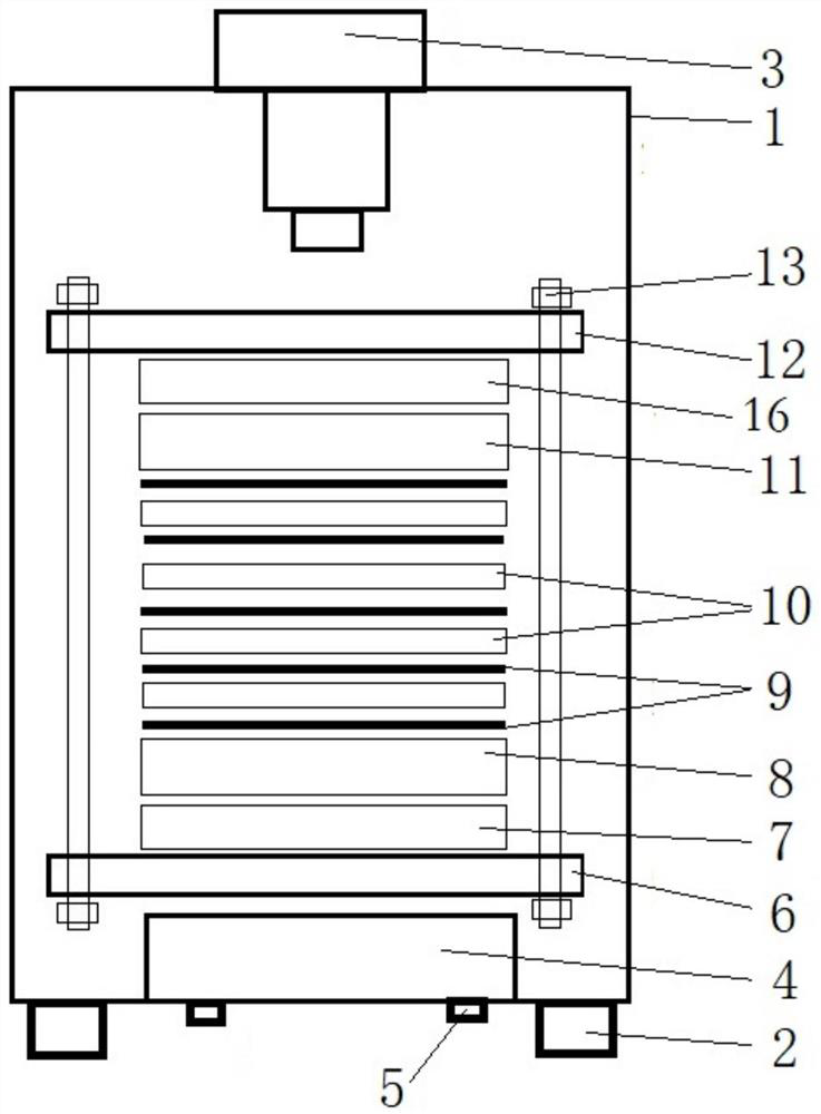
[0046] A vertical assembly device for a molten carbonate fuel cell stack provided in this embodiment, such as figure 1 As shown, including the frame 1, the bottom of the frame 1 is connected with several leveling feet 2, and the bottom surface of the frame 1 is connected with the bottom plate 4 through the leveling nut 5, and the bottom plate 4 can be realized by adjusting the leveling nut 5. and a horizontal state; the bottom plate 4 is provided with a lower pressing plate 6 among the pressing plates, a lower insulating plate 7 is arranged on the upper end of the lower pressing plate 6, a lower end plate 8 is arranged on the upper end of the lower insulating plate 7, and a battery stack is placed on the upper end of the lower end plate 8 An upper end plate 11, an upper insulating plate 16, and an upper pressing plate 12 are correspondingly arranged at the upper end and the lower end of the battery stack; a driving device 3 is arranged at the upper end of the frame 1, and the d...
Embodiment 2
[0051] The molten carbonate fuel cell stack vertical assembly method provided in this embodiment is applicable to the area less than 0.6m 2 , a molten carbonate fuel cell stack with less than 120 layers;
[0052] S1, after adjusting the level of the bottom plate 4 through the leveling nut 5, place the lower pressure plate 6, the lower insulating plate 7 and the lower end plate 8 on the bottom plate 4 in sequence, and adjust the level as a whole;
[0053] S2, assembling the molten carbonate fuel cell and other accessories on the lower insulating plate 7 according to the assembly order;
[0054] Specifically, the electrolyte diaphragm 9 and the bipolar plate 10 are stacked horizontally in sequence, and the upper end plate 11, the upper insulating plate 16 and the upper pressing plate 12 are placed horizontally on the last electrolyte diaphragm 9, and the upper and lower pressing plates 6 of the battery stack are tightened. The screw rods 13 are connected together; and the level...
PUM
| Property | Measurement | Unit |
|---|---|---|
| Area | aaaaa | aaaaa |
Abstract
Description
Claims
Application Information