
Girth welding device and girth welding method for tubeless engineering rims

A wheel rim and engineering technology, applied in welding equipment, welding equipment, auxiliary welding equipment, etc., can solve the problems of affecting welding quality, high labor cost, and low welding efficiency, so as to reduce labor dependence, facilitate loading and unloading, and improve The effect of welding efficiency

Pending Publication Date: 2021-08-10
ZHEJIANG HONGYUAN WHEEL
View PDF0 Cites 1 Cited by
  • Summary
  • Abstract
  • Description
  • Claims
  • Application Information

AI Technical Summary

Problems solved by technology

During the welding process, the joints between the inner rim and the intermediate connecting cylinder, and the joint between the intermediate connecting cylinder and the groove ring need to be welded on the inside and outside, so if manual welding is used, it is necessary to perform four rounds of welding in succession. It can be completed, but the welding efficiency is low, it takes a long time, the labor cost is high, and the welding quality cannot be guaranteed
Using an automated welding robot for welding can save labor, improve welding efficiency and ensure welding quality, but it also requires four rounds of welding to complete the welding
Whether it is manual welding or automated robot welding, the welding process needs to complete four rounds of welding successively. During this process, the position and state of the inner rim, intermediate connecting cylinder and groove ring need to be strictly controlled, otherwise the welding quality will be easily affected and the operation will be difficult. Big

Method used


Image

  • Girth welding device and girth welding method for tubeless engineering rims
  • Girth welding device and girth welding method for tubeless engineering rims
  • Girth welding device and girth welding method for tubeless engineering rims

Examples


Embodiment Construction

[0021] The technical solutions of the present invention will be clearly and completely described below in conjunction with the accompanying drawings. Apparently, the described embodiments are some of the embodiments of the present invention, but not all of them. Based on the embodiments of the present invention, all other embodiments obtained by persons of ordinary skill in the art without making creative efforts belong to the protection scope of the present invention.

[0022] In the description of the present invention, it should be noted that the terms "center", "upper", "lower", "left", "right", "vertical", "horizontal", "inner", "outer" etc. The indicated orientation or positional relationship is based on the orientation or positional relationship shown in the drawings, and is only for the convenience of describing the present invention and simplifying the description, rather than indicating or implying that the referred device or element must have a specific orientation, ...


PUM


Abstract

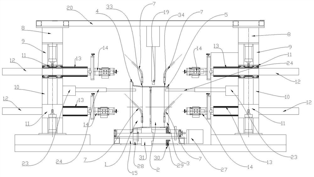
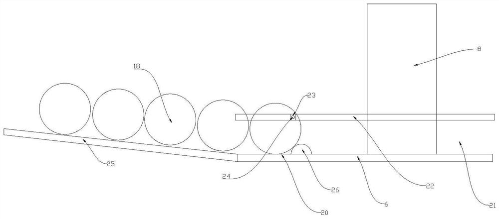
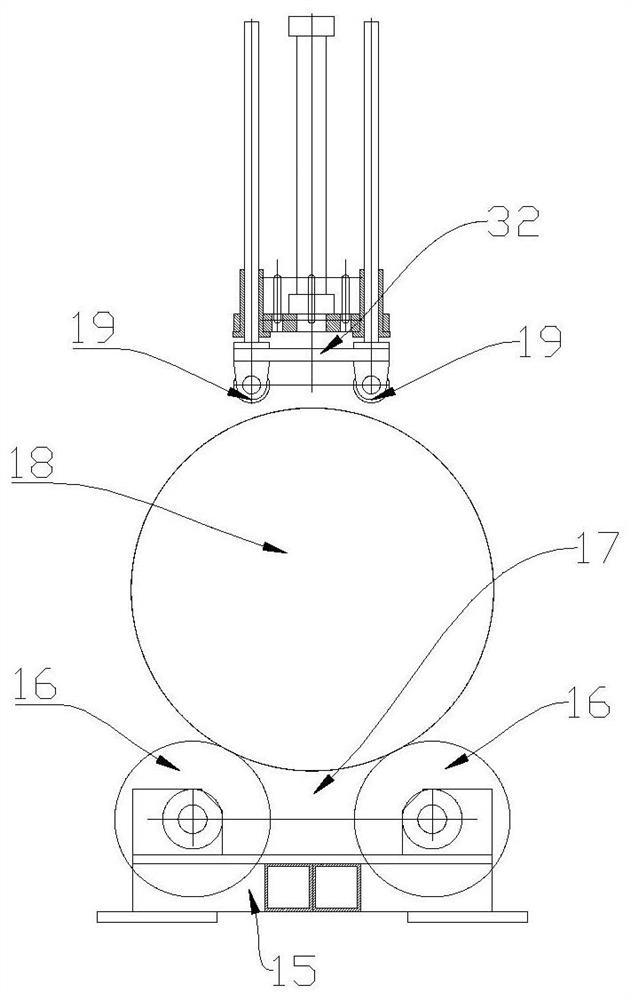
The invention discloses a girth welding device and girth welding method for tubeless engineering rims. The girth welding device comprises a base and four electric welding devices, each electric welding device comprises a welding gun, a rim supporting seat is arranged on the base, a welding position is arranged on the rim supporting seat, a liftable electric conduction pressing wheel is arranged above the welding position, and the electric conduction pressing wheel is electrically connected with all the electric welding devices. The girth welding method comprises the steps of pre-welding, feeding, welding gun in-place, girth welding and discharging. According to the girth welding device and girth welding method for the tubeless engineering rim, a simultaneous staggered girth welding mode is adopted for welding, the welding efficiency of the tubeless engineering rim is improved, the problem of the simultaneous welding process of multi-section workpieces is solved, and the welding quality of the rim can be effectively ensured. Feeding and discharging of the girth welding device are convenient and fast, and the manual dependence degree in the welding process is further reduced.

Description

technical field [0001] The invention belongs to the technical field of wheel rim production, and in particular relates to ring welding equipment and a ring welding method for tubeless engineering wheel rims. Background technique [0002] The tubeless engineering rim is composed of inner rim, intermediate connecting cylinder and groove ring welded in sequence. One side of the inner rim is expanded to form the inner rim, and the other side is welded with the intermediate connecting cylinder. The groove ring is provided with an annular groove. During the welding process, the joints between the inner rim and the intermediate connecting cylinder, and the joint between the intermediate connecting cylinder and the groove ring need to be welded on the inside and outside, so if manual welding is used, it is necessary to perform four rounds of welding in succession. It can be completed, but the welding efficiency is low, it takes a long time, the labor cost is high, and the welding qu...

Claims


Application Information

Patent Timeline
Patent Type & Authority Applications(China)
IPC IPC(8): B23K31/02B23K37/00B23K37/02B23K37/04B23K37/047
CPCB23K31/02B23K37/00B23K37/0252B23K37/0426B23K37/047
Inventor 肖海
Owner ZHEJIANG HONGYUAN WHEEL
Learn More