
Foundation pile drilling machine

A technology for drilling rigs and foundation piles, which is applied in the direction of rotary drilling rigs, earthwork drilling, drilling equipment, etc. It can solve the problems of easy swing and damage of auger drill pipes, and achieve vertical downward drilling, slow down friction, and lift The effect of stability

Pending Publication Date: 2021-08-10
上海振力工程机械设备有限公司
View PDF0 Cites 0 Cited by
  • Summary
  • Abstract
  • Description
  • Claims
  • Application Information

AI Technical Summary

Problems solved by technology

[0003] In view of the above-mentioned related technologies, the inventor believes that the length of the auger rod is usually more than two meters, and the power element that clamps and drives the auger rod to rotate is located at a position above two meters from the ground, and the power element that drives the auger rod to rotate the hole During the process, the auger rod is easy to swing, which can easily damage the driving elements that drive the auger rod to rotate

Method used


Image

  • Foundation pile drilling machine
  • Foundation pile drilling machine
  • Foundation pile drilling machine

Examples


Embodiment 1

[0032] The embodiment of the application discloses a foundation pile drilling machine.

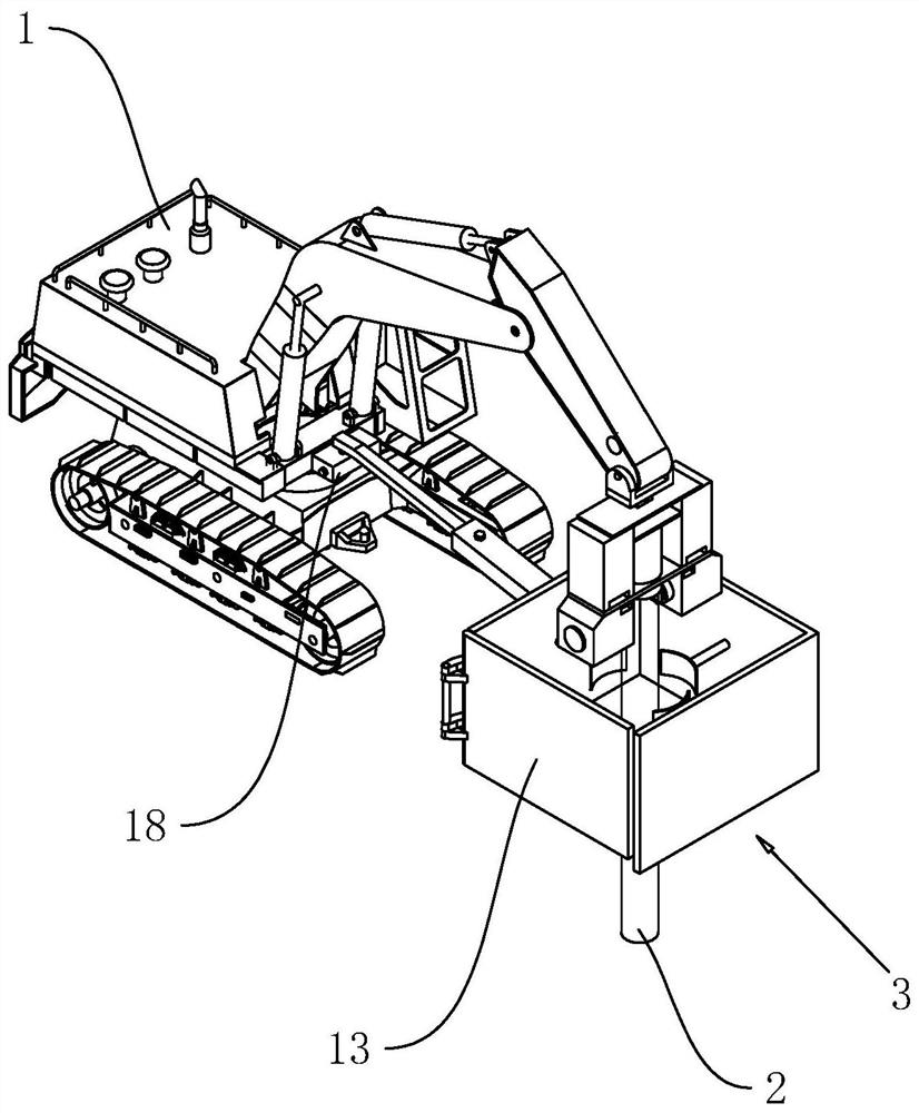
[0033] refer to figure 1 , a foundation pile drilling rig, including a body 1 and a drill pipe 2, the body 1 is the same as the body 1 of an excavator, and a clamp for clamping the drill rod 2 is fixedly installed on the mechanical arm of the body 1, and the clamp can make the clamped The drill pipe 2 rotates, and during the piling process, the drill pipe 2 is hoisted in advance by the mechanical arm to be in a vertical state.

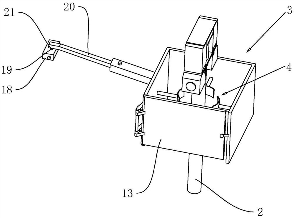
[0034] refer to figure 1 and figure 2 , the bottom of the drill pipe 2 is provided with a support frame 3, the support frame 3 is a rectangular frame, the support frame 3 is fixed on the ground, the side wall of the body 1 is provided with a mounting seat 18, and the mounting seat 18 is fixed at the lower end of the mechanical arm of the body 1 On the side wall, during the rotation process of the mechanical arm of the body 1, the mounting seat 18 rotates synchr...

Embodiment 2

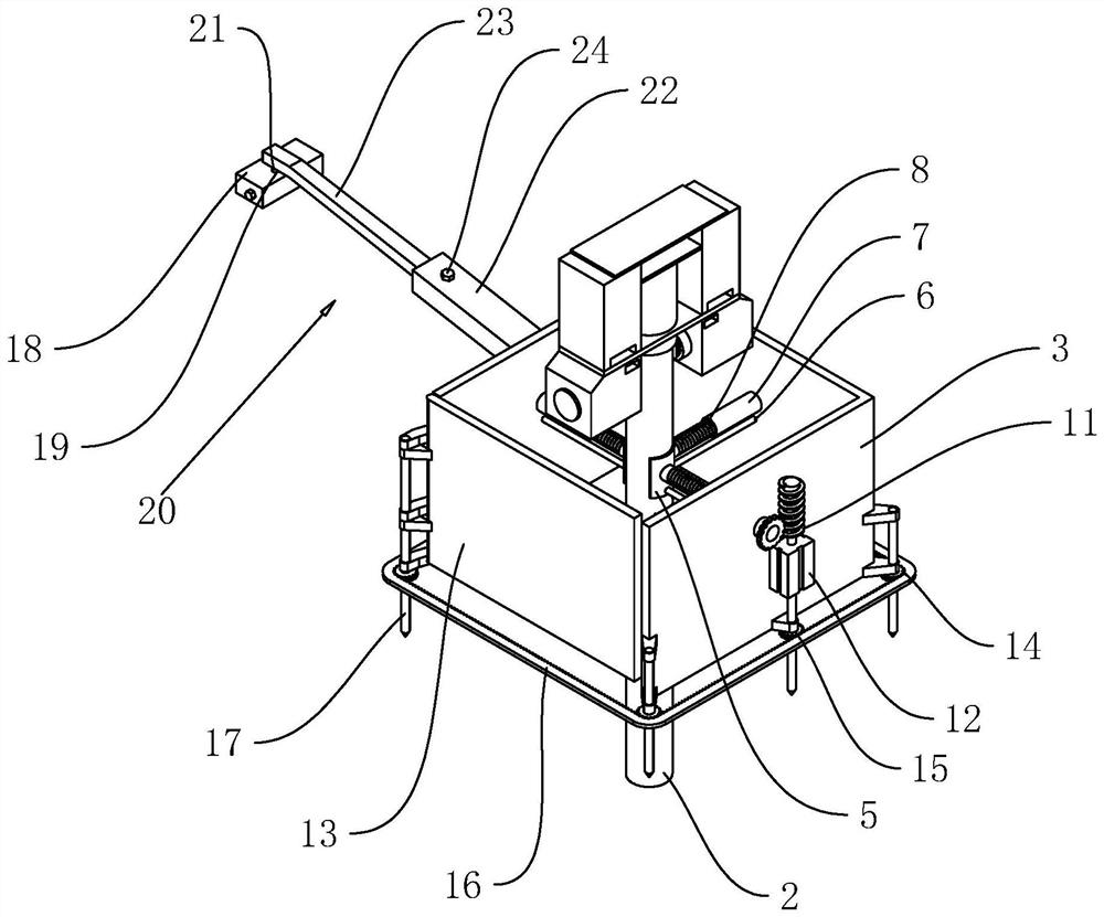
[0039] refer to image 3 and Figure 4The difference between the second embodiment and the first embodiment is that the limit assembly 4 includes an arc-shaped plate 5, a guide rod 6, a guide tube 7, a screw rod 8 and is arranged at the end of the guide tube 7 away from the arc-shaped plate 5 to drive the guide rod 6 to slide There are three driving parts 9 and three arc-shaped plates 5, and the three arc-shaped plates 5 are respectively arranged on the inner side walls of the support frame 3 without openings, and several balls 25 are arranged on the inner walls of the arc-shaped plates 5 to rotate evenly at intervals. During the construction process, where the outer wall of the ball 25 meets the outer wall of the drill pipe 2, the ball 25 slows down the friction between the inner wall of the arc-shaped plate 5 and the outer wall of the drill pipe 2, making it easier for the drill pipe 2 to drill vertically downward. The rod 6 slides on the support frame 3 along the direction...


PUM


Abstract

The invention relates to the technical field of foundation pile drilling, in particular to a foundation pile drilling machine. The foundation pile drilling machine comprises a machine body and a drill rod; a supporting frame is arranged on the machine body and located under a drill rod driving element; the upper end and the lower end of an inner cavity of the supporting frame communicate with the outside; the drill rod vertically penetrates into the inner cavity of the supporting frame; a limiting assembly used for limiting swing of the drill rod is arranged in the inner cavity of the supporting frame; and when the drill rod drills holes, the supporting frame is supported on the ground. The drilling machine has the effects that in the construction process, the peripheral side of a foundation pile is limited, so that the foundation pile is not prone to large-amplitude swing in the rotating process, and the stability of the piling process is improved.

Description

technical field [0001] The present application relates to the technical field of foundation pile drilling, in particular to a foundation pile drilling rig. Background technique [0002] Pile drilling rigs are often used to drill holes in existing foundation pile projects. The foundation pile drilling rig mainly includes a body and an auger drill rod for drilling. According to the hole diameter to be drilled, an auger rod with a suitable diameter is selected and installed on the body. Make the drill bit of the auger drill pipe vertically downward and rotate to realize drilling on the ground. [0003] In view of the above-mentioned related technologies, the inventor believes that the length of the auger rod is usually more than two meters, and the power element that clamps and drives the auger rod to rotate is located at a position more than two meters away from the ground, and drives the auger rod to rotate to drill the hole. During the process, the auger rod is easy to swin...

Claims


Application Information

Patent Timeline
Patent Type & Authority Applications(China)
IPC IPC(8): E21B7/02E21B3/02E21B15/00
CPCE21B3/02E21B7/02E21B15/00
Inventor 杨运福戴澄宇
Owner 上海振力工程机械设备有限公司
Learn More