Cooling structure of high-pressure moving blade of turbine of gas turbine

A technology of gas turbine and cooling structure, which is applied to the supporting elements of blades, machines/engines, mechanical equipment, etc., can solve the problems of increased cold air flow resistance, reduced cold air cooling capacity, small chamber area, etc., and achieves uniform temperature field. Low cold air flow, easy to manufacture effect

Active Publication Date: 2021-08-10
HANGZHOU TURBINE POWER GRP
View PDF5 Cites 7 Cited by
  • Summary
  • Abstract
  • Description
  • Claims
  • Application Information

AI Technical Summary

Problems solved by technology

However, this solution has the following defects: the cooling chamber is divided too much, and the area of ​​the chamber is too small, resulting in a large flow resistance of the cold air, and the pressure requirement of the cooling air supply is too high; the cooling air at the trailing edge of the blade has been heated upstream, and the cooling air The cooling capacity is greatly reduced, resulting in a decrease in the cooling performance of the trailing edge; the structure is too complicated; the manufacturing cost and difficulty are high
[0005] 1. Manufacturing is difficult and costly;
[0006] 2. For some positions, such as the cooling of the trailing edge of the blade is not sufficient, the cooling effect is not good enough;
[0007] 3. The pressure demand for air-conditioning supply is too high, and the air supply of cooling air is difficult

Method used


Image

  • Cooling structure of high-pressure moving blade of turbine of gas turbine
  • Cooling structure of high-pressure moving blade of turbine of gas turbine
  • Cooling structure of high-pressure moving blade of turbine of gas turbine

Examples


Embodiment 1

[0069] This embodiment is a cooling structure for the first-stage moving blade of a heavy-duty gas turbine turbine.

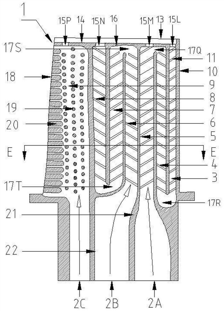
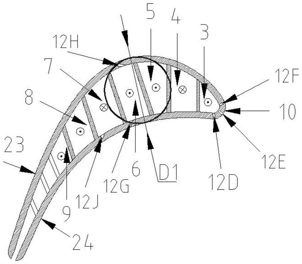
[0070] refer to figure 1 and figure 2 , is the front view and left view of the cooling structure of the first-stage rotor blade of a gas turbine turbine. In this embodiment, the height of the profile part of the blade is 5.50D1, the chord length is 4.05D1, and the axial chord length is 3.11D1, wherein D1 is the maximum thickness of the blade profile.

[0071] refer to figure 1 , there are three air inlets 2A, 2B and 2C at the bottom of the blade, and these three air inlets are evenly arranged at the root of the blade along the axial direction. The third channel, the second channel and the first channel are connected in sequence to form a serpentine channel, and the joints of adjacent channels form a U-shaped space; the fourth channel, the fifth channel and the sixth channel are connected in sequence to form a serpentine channel, adjacent A U-shaped space i...


PUM


Abstract

The invention provides a cooling structure of a high-pressure moving blade of a turbine of a gas turbine, and belongs to the technical field of gas turbines. The cooling structure is characterized in that seven channels including a first channel, a second channel, a third channel, a fourth channel, a fifth channel and a sixth channel are sequentially formed in the blade from the front edge of the blade to the tail edge of the blade; the first channel, the second channel, the third channel, the fourth channel, the fifth channel and the sixth channel are provided with turbulent flow ribs, the third channel, the second channel and the first channel are sequentially connected with one another to form a snakelike channel, U-shaped spaces are formed at joints of the adjacent channels, the fourth channel, the fifth channel and the sixth channel are sequentially connected with one another to form a snakelike channel, and U-shaped spaces are formed at joints of the adjacent channels; a first gas inlet, a second gas inlet and a third gas inlet are formed in the bottoms of the third channel, the fourth channel and the seventh channel; a plurality of split seams are formed in the tail edge of the blade, and gas can be exhausted via the split seams; a blade top groove is formed in a blade top, and cooling holes and process holes are formed in the blade top groove; and blade top pressure surface cooling holes are formed in a blade top pressure surface. The cooling structure has the advantages that the front edge of the blade, a suction surface of the blade, the blade top and the like can be sufficiently cooled, accordingly, uniform blade root temperature fields can be guaranteed, the temperature of a blade body can be reasonably distributed, and the cooling structure is low in cold gas flow.

Description

technical field [0001] The invention relates to the technical field of gas turbines, in particular to a cooling structure for high-pressure moving blades of a gas turbine turbine. Background technique [0002] Increasing the gas temperature is the most effective way to increase the efficiency and workability of the gas turbine. At present, the gas inlet temperature of advanced heavy-duty gas turbines has reached 1600°C, which is much higher than the service temperature of the blade material. Therefore, efficient turbine blade cooling must be designed structure, using as little cooling air flow as possible to cool the blades to acceptable temperature levels. The heat load of the high-pressure moving blade of the gas turbine is very high, the diameter of the leading edge is small, and the heat transfer coefficient is very large, which can reach 2 to 4 times the average heat transfer coefficient of the outer surface of the blade. This makes the leading edge area of ​​the turbi...

Claims


Application Information

Patent Timeline
Patent Type & Authority Applications(China)
IPC IPC(8): F01D5/18
CPCF01D5/186F01D5/187Y02T50/60
Inventor 王博隋永枫蓝吉兵任晟吴宏超陈列姚世传初鹏
Owner HANGZHOU TURBINE POWER GRP
Why Eureka
Try Eureka