Air film hole inlet and outlet groove structure for lap joint laminate contact surface

A technology of air film holes and contact surfaces, which is applied in the direction of engine components, machines/engines, mechanical equipment, etc., can solve the problems of incomplete overlap, misalignment, and the cooling efficiency of straight air film holes is not as good as that of oblique air film holes, etc., to improve processing Effect of error margin, reduction of processing difficulty, and improvement of cooling effect

Inactive Publication Date: 2021-08-10
BEIHANG UNIV
View PDF6 Cites 0 Cited by
  • Summary
  • Abstract
  • Description
  • Claims
  • Application Information

AI Technical Summary

Problems solved by technology

Due to the existence of objective factors such as positioning errors and remelting layers, the inlet and outlet of the corresponding air film holes on the contact surface of the laminates often cannot be completely overlapped during assembly, and there is a certain degree of misalignment, which makes it impossible for some air film hole flow paths to be completely penetrated. , making film cooling less effective than expected
[0005] In order to avoid the misalignment of air film holes as far as possible in engineering, it is often avoided to design oblique air film holes on the overlapping laminates, but to choose relatively better positioned straight air film holes, which can reduce the probability of perforation misplacement and at the same time Improve the reliability of the air film hole, but the cooling efficiency of the straight air film hole is not as good as that of the oblique air film hole

Method used


Image

  • Air film hole inlet and outlet groove structure for lap joint laminate contact surface
  • Air film hole inlet and outlet groove structure for lap joint laminate contact surface
  • Air film hole inlet and outlet groove structure for lap joint laminate contact surface

Examples


Embodiment Construction

[0021] In order to understand the above-mentioned purpose, features and advantages of the present invention more clearly, the present invention will be further described in detail below in conjunction with the accompanying drawings and specific embodiments. It should be noted that, in the case of no conflict, the embodiments of the present invention and the features in the embodiments can be combined with each other.

[0022] In the following description, many specific details are set forth in order to fully understand the present invention. However, the present invention can also be implemented in other ways different from those described here. Therefore, the protection scope of the present invention is not limited by the specific details disclosed below. EXAMPLE LIMITATIONS.

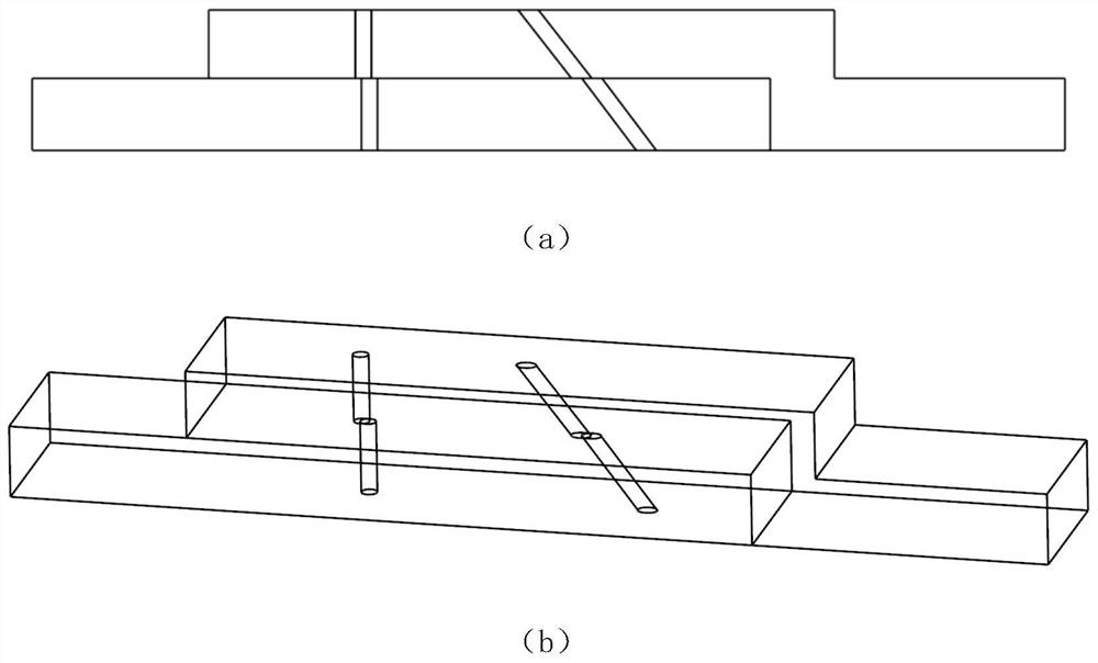
[0023] figure 1 For the misalignment of the corresponding air film holes caused by positioning errors and other factors when the air film holes are made on the overlapping laminates in the project. F...


PUM

PropertyMeasurementUnit
depthaaaaaaaaaa
diameteraaaaaaaaaa
diameteraaaaaaaaaa

Abstract

The invention discloses an air film hole inlet and outlet groove structure for a lap joint laminate contact surface. The air film hole inlet and outlet groove structure for the lap joint laminate contact surface is characterized in that an air film hole inlet and an air film hole outlet on the laminate contact surface with punched air film holes are subjected to hole diameter expansion treatment, that is, grooves are independently processed at the inlet and outlet positions, and then two laminates are overlapped and assembled. The grooves can be processed into a plurality of shapes, such as a conical shape, a cylindrical shape and a semispherical shape, and a proper groove shape can be selected according to specific conditions of a punching tool and the like. According to the air film hole inlet and outlet groove structure for the lap joint laminate contact surface, the corresponding air film holes in the lap joint laminates can effectively communicate, the problem that the corresponding air film holes of the two laminates are staggered due to processing errors is solved, and therefore the air film cooling effect on the lap joint laminates is guaranteed.

Description

technical field [0001] The invention belongs to the technical field of aero-engines and thermal protection, and in particular relates to an inlet and outlet groove structure for air film holes on the contact surface of overlapping laminates. Background technique [0002] At present, the turbine inlet temperature of aero-engine continues to increase, and the turbine outlet temperature also increases accordingly. As the downstream part of the turbine, the rear casing bears the mechanical load of the engine on the one hand, and the thermal load brought by the high-temperature gas at the turbine outlet on the other hand. Therefore, it is necessary to cool the rear casing to ensure its safe and reliable operation. . [0003] Film cooling is widely used in the cooling process of the rear receiver. The processing methods of gas film holes mainly include laser drilling, electric spark drilling, electro-hydraulic beam drilling, etc., each method has its own advantages and disadvant...

Claims


Application Information

Patent Timeline
Patent Type & Authority Applications(China)
IPC IPC(8): F01D25/12F01D25/14
CPCF01D25/12F01D25/14
Inventor 邱天丁水汀王承昊刘传凯刘晓静
Owner BEIHANG UNIV
Why Eureka
Try Eureka