
Visual inspection system

A technology of visual inspection and mounting frame, which is applied in the field of visual inspection system, can solve the problems of low efficiency of lens calibration and achieve the effect of improving versatility and calibration efficiency

Pending Publication Date: 2021-08-10
CHINA RAILWAY CONSTR HEAVY IND
View PDF11 Cites 0 Cited by
  • Summary
  • Abstract
  • Description
  • Claims
  • Application Information

AI Technical Summary

Problems solved by technology

[0005] The purpose of the present invention is to provide a visual inspection system to solve the problem of low lens calibration efficiency in the aggregate inspection process

Method used


Image

  • Visual inspection system
  • Visual inspection system
  • Visual inspection system

Examples


Embodiment

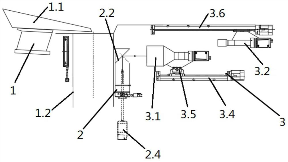
[0037] see Figure 1 to Figure 6 , a visual inspection system, this embodiment is applied to lens calibration and aggregate inspection of a visual inspection system.

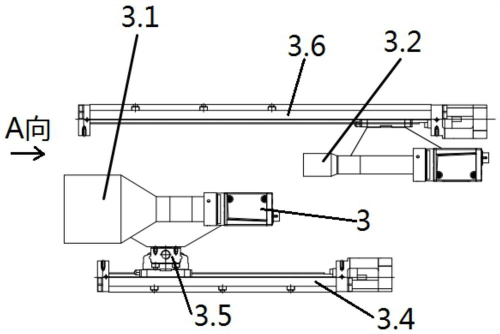
[0038] A visual detection system comprising a blanking unit 1, a calibration unit 2, an image acquisition unit 3 and a control unit; the blanking unit 1, the calibration unit 2 and the image acquisition unit 3 are all connected to the control unit by signals;

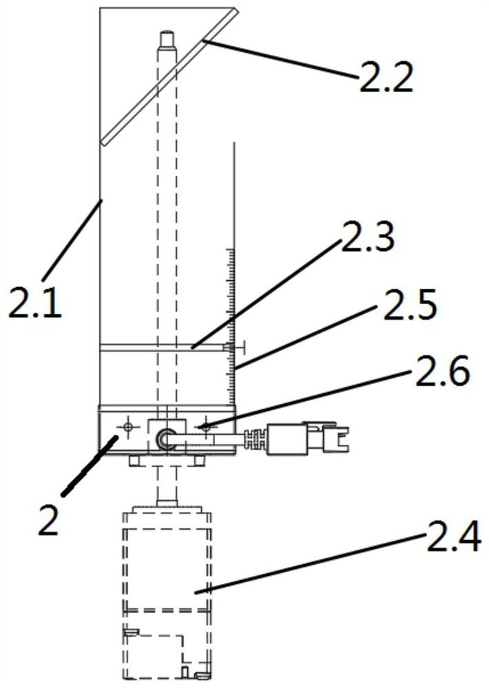
[0039] see Figure 1 to Figure 2 , the calibration unit 2 includes a mounting frame 2.1, a mirror 2.2, and a calibration plate 2.3; the calibration plate 2.3 is horizontally arranged on the mounting frame 2.1, and a pattern array with a fixed spacing is provided on the calibration plate 2.3 for visual Calibration of the detection system: the reflective mirror 2.2 is arranged on the mounting frame 2.1, and the reflective mirror 2.2 is located above the calibration plate 2.3, and the reflective mirror 2.2 is at an angle of 45° with the horizontal plane; th...


PUM


Abstract

The invention provides a visual inspection system. The system comprises a blanking unit, a calibration unit, an image acquisition unit and a control unit, the blanking unit, the calibration unit and the image acquisition unit are all in signal connection with the control unit; the calibration unit comprises a mounting frame, a reflective mirror and a calibration plate; the calibration plate is horizontally arranged on the mounting rack; the reflective mirror is arranged on the mounting frame and located above the calibration plate, and an included angle of 45 degrees is formed between the reflective mirror and the horizontal plane; and the reflective mirror is used for cooperating with the image acquisition unit to realize image acquisition and calibration. The blanking unit, the calibration unit and the image acquisition unit are all in signal connection with the control unit, and an image of a pattern array on a calibration plate is transmitted to the image acquisition unit through a reflective mirror according to a reflection principle; and the calibration plate does not need to be arranged in the aggregate passing area, the image on the calibration plate can be transmitted to the image acquisition unit for automatic calibration, and the calibration efficiency is improved.

Description

technical field [0001] The invention relates to the technical field of industrial detection, in particular to a visual detection system. Background technique [0002] At present, in the image calibration and gravel detection work in the field of industrial inspection technology, the purpose of calibration work is to correct lens distortion and determine the conversion relationship between physical size and pixel. Especially in the gravel production line, when inspecting aggregates of different specifications, due to the different field of view required, it is necessary to replace the appropriate lens for inspection, and calibration is required every time the lens is replaced. This stage is crucial to the subsequent detection. If the calibration is not good, the image detection results will be inaccurate, which will affect the judgment of the quality of the finished aggregate. [0003] At present, the calibration work of the lens is generally carried out manually, the calibr...

Claims


Application Information

Patent Timeline
Patent Type & Authority Applications(China)
IPC IPC(8): G01N21/84G06T7/80
CPCG01N21/84G06T7/80G01N2021/015
Inventor 刘飞香廖金军王金锋秦念稳胡星科王旭
Owner CHINA RAILWAY CONSTR HEAVY IND
Learn More