Supercharge Your Innovation With Domain-Expert AI Agents!

Liquid crystal display panel and electronic equipment

A technology for liquid crystal display panels and electronic equipment, applied in nonlinear optics, instruments, optics, etc., can solve the problems of low reflectivity and high production cost of liquid crystal display panels, achieve increased area, reduce mold opening costs and production costs, and reduce cost effect

Pending Publication Date: 2021-08-10
TRULY SEMICON
View PDF0 Cites 0 Cited by
  • Summary
  • Abstract
  • Description
  • Claims
  • Application Information

AI Technical Summary

Problems solved by technology

[0004] The invention discloses a liquid crystal display panel and electronic equipment, which are used to solve the problems of high production cost and low reflectivity of the liquid crystal display panel in the prior art

Method used


Image

  • Liquid crystal display panel and electronic equipment
  • Liquid crystal display panel and electronic equipment
  • Liquid crystal display panel and electronic equipment

Examples


Embodiment 1

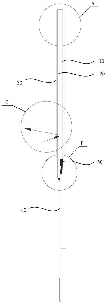
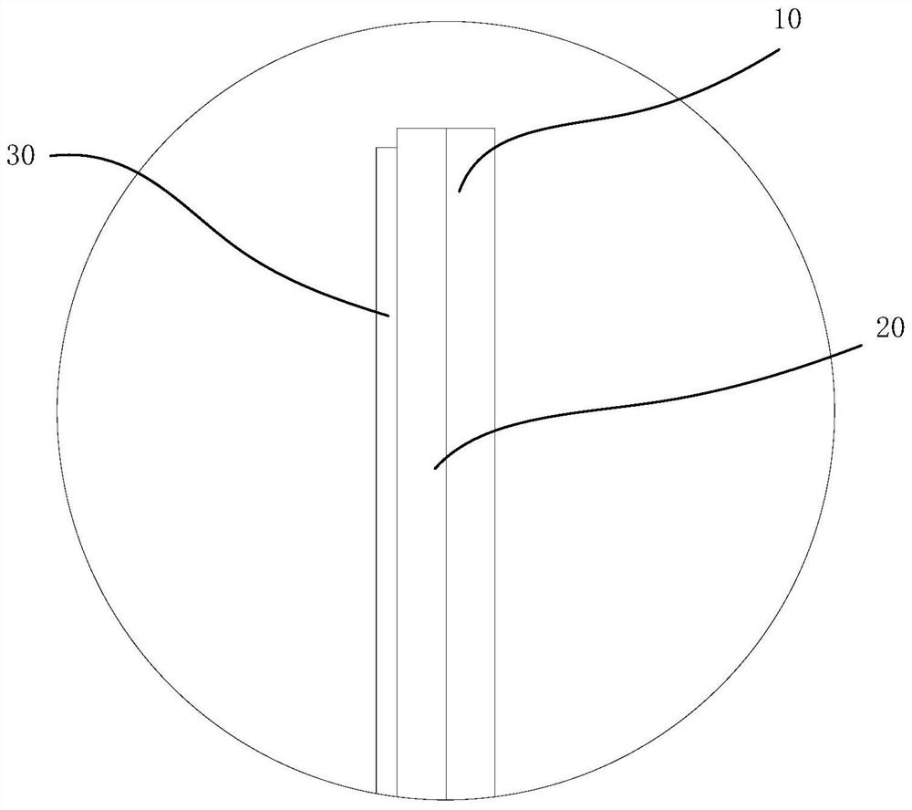
[0034] Such as figure 1 , image 3 and Figure 4 As shown, the liquid crystal display panel provided by the present invention includes a reflective module, and the reflective module includes a filter substrate 10 and an array substrate 20 arranged in layers.

[0035] The filter substrate 10 includes a plurality of filter units distributed in an array, no black matrix is ​​arranged between adjacent filter units, and the adjacent filter units are in direct contact with each other. Since the setting of the black matrix has a great influence on the pixel aperture ratio. Therefore, the black matrix is ​​removed, the area of ​​reflected light is increased, and the mold opening cost and production cost of the filter substrate 10 are reduced.

[0036] The liquid crystal display panel further includes: a polarizer 30 at least partially covering the array substrate; a flexible circuit board 40 at least partially overlapping the array substrate 20 ; a driving integrated circuit 50 at ...

Embodiment 2

[0043] This embodiment provides an electronic device, including the liquid crystal display panel in Embodiment 1.

[0044] It also includes a backlight module. The backlight module is arranged on the side of the filter substrate 10 away from the array substrate 20. The backlight module is used to provide a backlight for electronic equipment.

[0045] Such as Figure 5 As shown, the backlight module includes a light source and a light guide plate. The light emitted by the light source is guided through the light guide plate, passes through the polarizer 30 and the filter substrate 10 in the liquid crystal display panel, and is reflected from the array substrate 20 . The screen reflectivity of this electronic device is high, the cost is low, and it has good market competitiveness.

[0046] The technical scheme adopted in the present invention can achieve the following beneficial effects:

[0047] (1) There is no black matrix between adjacent filter units on the filter substrat...


PUM


Abstract

The invention discloses a liquid crystal display panel which comprises a reflection module. The reflection module comprises a light filtering substrate and an array substrate which are arranged in a stacked mode. The light filtering substrate comprises a plurality of light filtering units distributed in an array mode, no black matrix is arranged between every two adjacent light filtering units, and every two adjacent light filtering units make direct contact. The liquid crystal display panel further comprises a polarizer which at least partially covers the array substrate; a flexible circuit board which is at least partially overlapped with the array substrate; and a driving integrated circuit which is at least partially overlapped with the array substrate. No black matrix is arranged between the adjacent light filtering units on the light filtering substrate, so that the area of reflected light is increased, and meanwhile, the mold opening cost and the manufacturing cost of the light filtering substrate are reduced. The array substrate is provided with a metal assembly, and the reflectivity is improved by utilizing the high white state reflection effect of the metal assembly. A transparent conductive film on the light filtering substrate is changed into a metal layer which can be used as a reflecting layer, and only one polarizer is needed, so that the cost is reduced, and meanwhile, the process loss of light is reduced.

Description

technical field [0001] The invention relates to the technical field of display panels, in particular to a liquid crystal display panel and electronic equipment. Background technique [0002] With the rise of smart homes, smart supermarkets, etc., there is an increasing demand for low-power, high-reflection, and low-cost products, such as electronic price tags and smart home appliances. The market still chooses products using electronic paper solutions. At present, ordinary liquid crystal products cannot achieve high reflectivity due to the use of conventional designs, and the cost is still high. [0003] In view of this, there is an urgent need to improve existing liquid crystal display panels to reduce production costs and increase reflectivity. Contents of the invention [0004] The invention discloses a liquid crystal display panel and electronic equipment, which are used to solve the problems of high manufacturing cost and low reflectivity of the liquid crystal displa...

Claims


Application Information

Patent Timeline
Patent Type & Authority Applications(China)
IPC IPC(8): G02F1/1335
CPCG02F1/133514G02F1/133528G02F1/133553
Inventor 廖亿彬
Owner TRULY SEMICON
Features
  • R&D
  • Intellectual Property
  • Life Sciences
  • Materials
  • Tech Scout
  • Unparalleled Data Quality
  • Higher Quality Content
  • 60% Fewer Hallucinations
Learn More