
Row driving circuit, driving method and display panel

A line driver and circuit technology, applied in static indicators, nonlinear optics, instruments, etc., can solve the problems that GDL circuit layout design cannot meet the requirements of frame specifications and the size becomes smaller, so as to reduce the number of transistors and reduce the space occupied. Effect

Pending Publication Date: 2021-08-10
MIANYANG HKC OPTOELECTRONICS TECH CO LTD +1
View PDF4 Cites 0 Cited by
  • Summary
  • Abstract
  • Description
  • Claims
  • Application Information

AI Technical Summary

Problems solved by technology

[0003] The current GDL circuit (array substrate line drive, Gate Driver Less) is applied to ultra-high-definition large-size products, but due to changes in customer consumption needs, factory technical requirements, and progress in process capabilities, the screen resolution is increased, the frame width is reduced, and the The screen-to-body ratio of the screen is a trend. For a screen of the same size, increasing the resolution means that the size of each pixel becomes smaller; this requires the GDL circuit to ensure performance and safety in a limited space, and to play its due role. Some functions; but due to design reasons, such as timing control and the control connection of multiple signals to transistors, the number of transistors in the GDL circuit is as many as dozens, resulting in the GDL circuit layout design not meeting the frame specifications. Requirements; therefore, it is necessary to re-modify the GDL circuit design to reduce the space occupied by the GDL circuit as much as possible under the condition of satisfying the driving capability, so as to meet the requirements of narrow frame and high resolution

Method used


Image

  • Row driving circuit, driving method and display panel
  • Row driving circuit, driving method and display panel
  • Row driving circuit, driving method and display panel

Examples


Embodiment Construction

[0034] It should be understood that the terminology and specific structural and functional details disclosed herein are representative only for describing specific embodiments, but the application can be embodied in many alternative forms and should not be construed as merely Be limited by the examples set forth herein.

[0035] In the description of the present application, the terms "first" and "second" are used for descriptive purposes only, and cannot be understood as indicating relative importance, or implicitly indicating the quantity of indicated technical features. Therefore, unless otherwise specified, the features defined as "first" and "second" may explicitly or implicitly include one or more of these features; "plurality" means two or more. The term "comprising" and any variations thereof mean non-exclusive inclusion, possible presence or addition of one or more other features, integers, steps, operations, units, components and / or combinations thereof.

[0036] Al...


PUM


Abstract

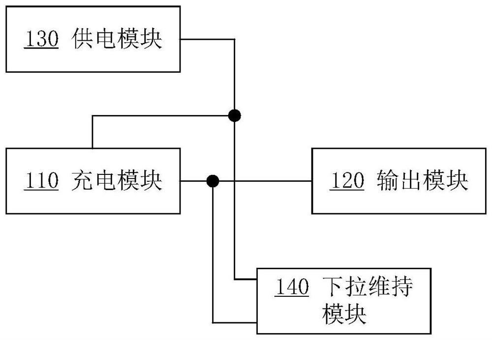
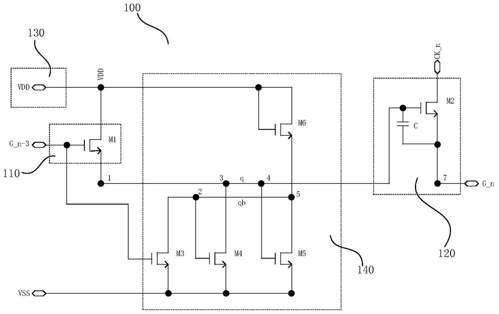
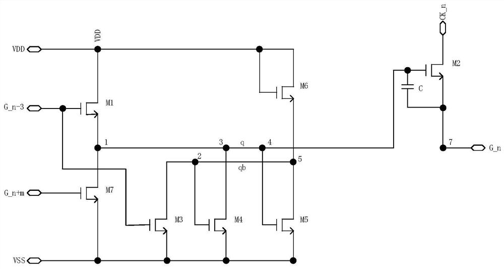
The invention discloses a row driving circuit, a driving method and a display panel. The row driving circuit comprises a charging module, an output module, a power supply module and a pull-down maintaining module, wherein the control end of the charging module is connected to a gate starting signal or a superior gate driving signal, the control end of the output module is connected with the output end of the charging module, the input end is connected with a current-stage clock signal, the power supply module provides continuous high level, the output end of the power supply module is connected with the input end of the charging module, the first control end of the pull-down maintaining module is connected to the output end of the power supply module, the second control end of the pull-down maintaining module is connected to the output end of the charging module, the input end of the pull-down maintaining module is connected to the output end of the charging module, and the output end of the pull-down maintaining module is connected with a standard low-level signal. According to the invention, the power supply module and the charging module are used for controlling the opening and closing of the pull-down maintaining module, so that the potential of the output end of the charging module is effectively lowered, other transistors controlled by a time sequence do not need to be arranged, the number of the transistors is reduced, and implementation of a narrow frame is facilitated.

Description

technical field [0001] The present application relates to the field of display technology, in particular to a row driving circuit, a driving method and a display panel. Background technique [0002] Liquid Crystal Display (LCD, Liquid Crystal Display) has many advantages such as thin body, power saving, and no radiation, so it has been widely used. Thinning development. [0003] The current GDL circuit (array substrate line drive, Gate Driver Less) is applied to ultra-high-definition large-size products, but due to changes in customer consumption needs, factory technical requirements, and progress in process capabilities, the screen resolution is increased, the frame width is reduced, and the The screen-to-body ratio of the screen is a trend. For a screen of the same size, increasing the resolution means that the size of each pixel becomes smaller; this requires the GDL circuit to ensure performance and safety in a limited space, and to play its due role. Some functions; b...

Claims


Application Information

Patent Timeline
Patent Type & Authority Applications(China)
IPC IPC(8): G02F1/1345G02F1/1368G09G3/36
CPCG02F1/13454G02F1/1368G09G3/3677
Inventor 李伟伟康报虹
Owner MIANYANG HKC OPTOELECTRONICS TECH CO LTD
Learn More