Turnover feeding type cooker
A cooking machine and material turning technology, which is applied to the structure of kitchen utensils, household utensils, cooking utensils, etc., can solve the problems of complex feeding structure, high cost of manipulator, inconvenient control, etc., to improve feeding efficiency, accurate and reliable feeding, The effect of short motion paths
- Summary
- Abstract
- Description
- Claims
- Application Information
AI Technical Summary
Problems solved by technology
Method used
Image
Examples
Embodiment 1
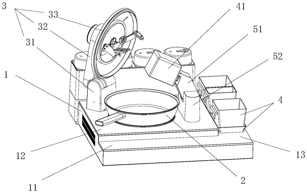
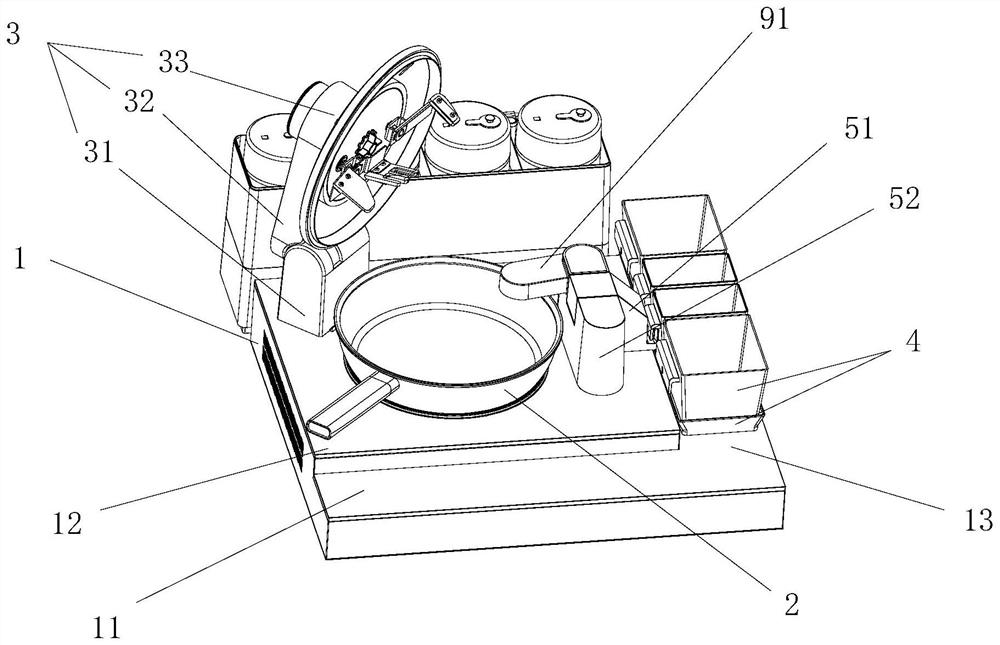
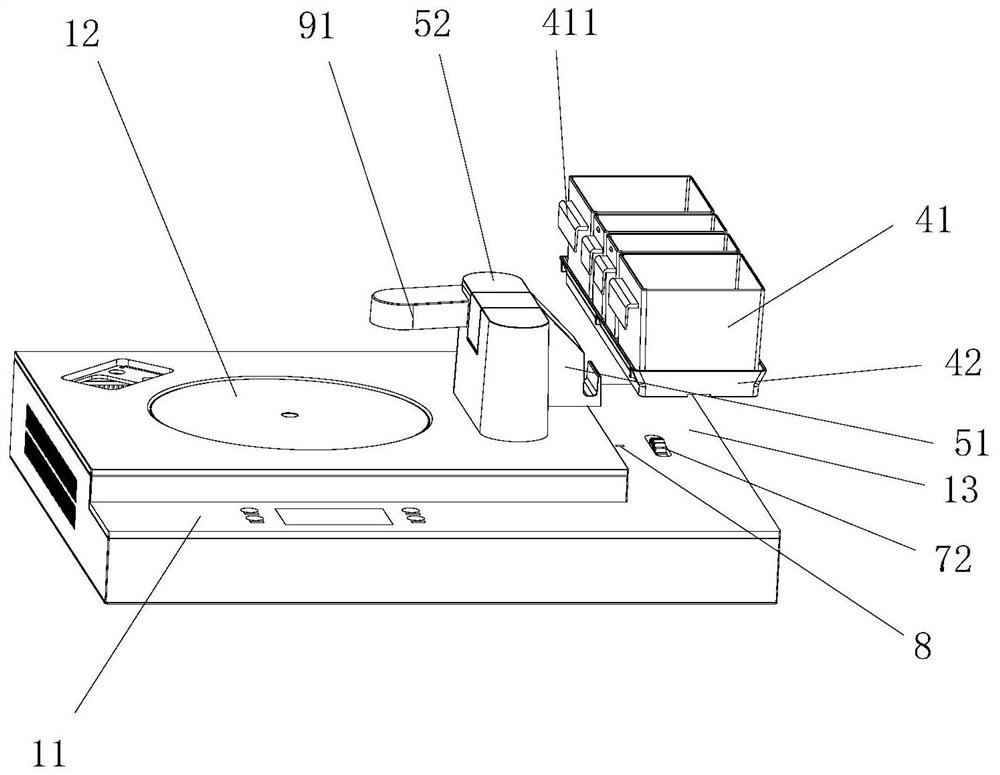
[0055] Such as Figure 1-Figure 14 As shown, this embodiment provides a flip-feeding type cooking machine, including a body 1, a pot 2, a pot cover assembly 3, a material box assembly 4 and a material turning swing arm assembly 5, and the material turning swing arm assembly 5 includes a material turning Swing arm 51, swing arm seat 52 and material turning drive device 53, pot cover assembly 3 comprises pot cover support 31, pot cover swing arm 32 and cover body 33, is provided with pot cover driving device in the pot cover support 31, pot The lid driving device drives the lid swing arm 32 to drive the lid body 33 to automatically cover and open the pot 2, so as to automatically add ingredients and seasonings. The body 1 has a control plane 11, a cooking plane 12 for placing the pot 2, and a material box 41 The material plane 13, the control plane 11 and the material plane 13 are arranged on the same plane, and the control plane 11 and the material plane 13 are respectively loc...
Embodiment 2
[0093] The difference between this embodiment and the first embodiment lies in that the structure of the turning arm control device is different.
[0094] Such as Figure 15 and Figure 16 As shown, the plectrum 541 is set coaxially with the output shaft, and the plectrum 541 is provided with two trigger protrusions 5413 at intervals, and the interval angle can be set according to needs. The first trigger protrusion 5413 rotates to a certain angle to squeeze the trigger rod 5431 to trigger the first micro switch 542. In this embodiment, the two trigger protrusions 5413 respectively trigger the first micro switch 542 in the initial state and the feeding state, so as to To stop the turning drive device 53 or switch the working state, two trigger protrusions 5413 are arranged on one trigger paddle to realize the integrated setting of trigger structures at two different positions, reducing space occupation and the number of parts. Other unexplained features and technical effects...
Embodiment 3
[0096] The difference between this embodiment and the first embodiment lies in that the structure of the turning arm control device is different.
[0097] In this embodiment, the turning arm control device includes a third microswitch 547 arranged on the swing arm seat 52, the third microswitch 547 is installed under the turning arm 51, and the turning arm 51 The retrieving position triggers the third microswitch 547. In this embodiment, the third microswitch 547 is installed on the support slope 5211, and the support surface 5123 triggers the third microswitch 547 at the retrieving position. Specifically, as Figure 17 and Figure 18 As shown, the third microswitch 547 is located below the elastic seal 522, and the supporting surface 5123 at the bottom of the turning arm 51 is provided with a protrusion, and the position of the protrusion corresponds to the third microswitch 547. When the turning arm When 51 rotates to the material retrieving position, the protrusion of the ...
PUM
 Abstract
Description
Claims
Application Information
 - R&D
- Intellectual Property
- Life Sciences
- Materials
- Tech Scout
- Unparalleled Data Quality
- Higher Quality Content
- 60% Fewer Hallucinations
Browse by: Latest US Patents, China's latest patents, Technical Efficacy Thesaurus, Application Domain, Technology Topic, Popular Technical Reports.
© 2025 PatSnap. All rights reserved.Legal|Privacy policy|Modern Slavery Act Transparency Statement|Sitemap|About US| Contact US: help@patsnap.com


