Eureka AIR delivers breakthrough ideas for toughest innovation challenges, trusted by R&D personnel around the world.

Magnetic collector and electromagnetic pulse forming device

A magnetic collector and magnetic collection technology, which is applied in the field of electromagnetic forming, can solve the problems of inconspicuous magnetic collection effect of the magnetic collector, reduced magnetic collection effect of the magnetic collector, and inability to ensure the effective collection of induced currents.

Inactive Publication Date: 2021-08-13
SHENZHEN AUTOMOTIVE RES INST BEIJING INST OF TECH (SHENZHEN RES INST OF NAT ENG LAB FOR ELECTRIC VEHICLES)
View PDF6 Cites 0 Cited by
  • Summary
  • Abstract
  • Description
  • Claims
  • Application Information

AI Technical Summary

Problems solved by technology

[0004] When welding plate-shaped workpieces, the magnetic collector is equivalent to a structure formed by the combination of component one and component two; on the one hand, the increase in the number of components will reduce the magnetic collection effect of the magnetic collector; on the other hand, this When the second component is equivalent to a conductor that can guide the induced current, it cannot guarantee that the induced current can be effectively collected to the end face of the second component, so that the magnetic effect of the magnetic collector is not obvious

Method used


Image

  • Magnetic collector and electromagnetic pulse forming device
  • Magnetic collector and electromagnetic pulse forming device
  • Magnetic collector and electromagnetic pulse forming device

Examples


Embodiment Construction

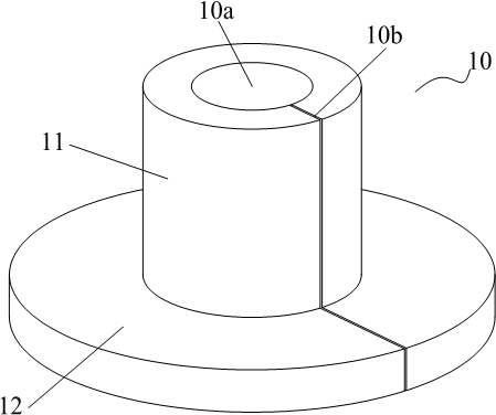
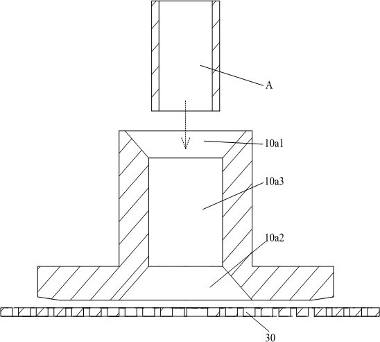
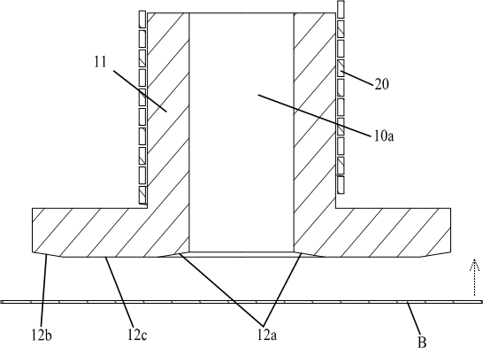
[0042]The present invention will be further described in detail below through specific embodiments in conjunction with the accompanying drawings. Wherein, similar elements in different implementations adopt associated similar element numbers. In the following implementation manners, many details are described for better understanding of the present application. However, those skilled in the art can readily recognize that some of the features can be omitted in different situations, or can be replaced by other elements, materials, and methods. In some cases, some operations related to the application are not shown or described in the description, this is to avoid the core part of the application being overwhelmed by too many descriptions, and for those skilled in the art, it is necessary to describe these operations in detail Relevant operations are not necessary, and they can fully understand the relevant operations according to the description in the specification and general...


PUM

PropertyMeasurementUnit
Widthaaaaaaaaaa

Abstract

The invention discloses an electromagnetic pulse forming device. The magnetic collector comprises a magnetic pulse generating part, a spiral pipe type coil, a spiral plate type coil and a magnetic collector body, wherein the spiral pipe type coil and the spiral plate type coil are arranged at the output end of the magnetic pulse generating part in parallel, the magnetic collector is connected to one of the spiral pipe type coil and the spiral plate type coil in a switchable combined mode, the magnetic collector body comprises a magnetic collection core body, the magnetic collection core body is provided with a flow guide kerf, a middle column part and an end plate part, when the magnetic collector body is switched to the combination of the middle column part and the spiral pipe type coil, the induced current can be collected to the end plate part by the flow guide kerf, when the magnetic collector body is switched to the combination of the end plate part and the spiral plate type coil, the flow guide kerf can collect the induced current to the middle column part. By means of the structural characteristics of the magnetic collector body, the forming device can be suitable for forming and processing plate-shaped and pipe-shaped workpieces only by switching the magnetic collector body between the spiral pipe type coil and the spiral plate type coil, the coils and related tool parts do not need to be replaced, the universality of the device is enhanced, and conditions are created for reducing the production cost and improving the processing efficiency.

Description

technical field [0001] The invention relates to the technical field of electromagnetic forming, in particular to a magnet collector and an electromagnetic pulse forming device. Background technique [0002] Electromagnetic pulse forming technology is a high-speed, high-energy, short-time pulse processing technology, which is widely used in the forming and processing of various workpieces such as crimping, welding, stamping, etc.; its basic principle is to use a capacitor bank to discharge the discharge coil , A transient strong magnetic field is generated due to the rapidly changing current flowing through the discharge coil, which makes the surface of the workpiece placed in it form an eddy current and deform under the action of the electromagnetic force. In this technology, the magnetic collector is a key device that is often used. [0003] At present, for the forming and processing of plate-shaped workpieces and tubular workpieces, it is usually necessary to pair a speci...

Claims


Application Information

Patent Timeline
IPC IPC(8): B21D26/14
CPCB21D26/14
Inventor 王智辉王文伟欧航李杰柳泉潇潇曾兵罗通
Owner SHENZHEN AUTOMOTIVE RES INST BEIJING INST OF TECH (SHENZHEN RES INST OF NAT ENG LAB FOR ELECTRIC VEHICLES)
Why Eureka
Eureka Blog
Learn More