
Lens and mold transfer system

A mold and lens technology, applied in the field of systems for transferring lenses and molds, can solve problems such as height difference, shorten cycle time, increase molding speed, and eliminate molding defects.

Active Publication Date: 2021-08-13
株式会社大镐技术
View PDF22 Cites 0 Cited by
  • Summary
  • Abstract
  • Description
  • Claims
  • Application Information

AI Technical Summary

Problems solved by technology

In the case of the sliding transfer method, there is a problem that it is difficult to connect the members for the mold to slide and transfer in the horizontal direction without steps, and if the mold is set to slide and transfer at an incline downward, there is a problem with the eventual The problem of height difference in the part where the mold is fed into the lens molding machine

Method used


Image

  • Lens and mold transfer system
  • Lens and mold transfer system
  • Lens and mold transfer system

Examples


Embodiment Construction

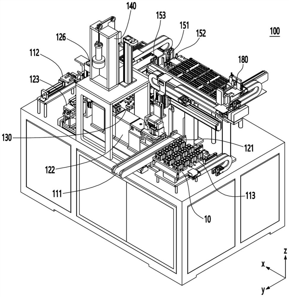
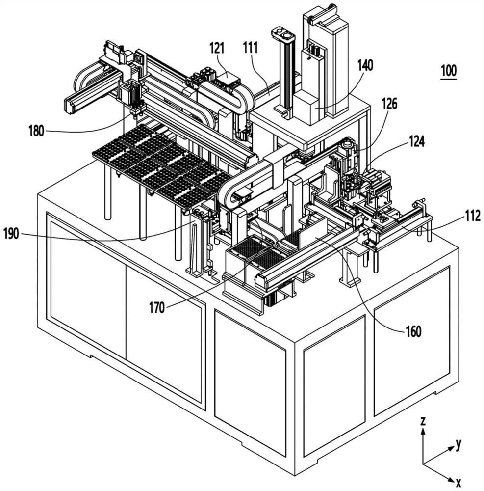
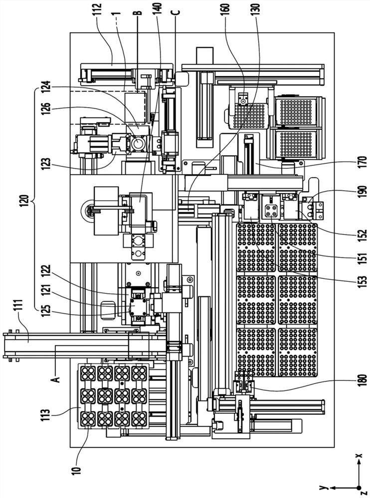
[0081] Next, the lens and mold transfer system will be described in more detail with reference to the drawings.

[0082] When describing the embodiments disclosed in this specification, if it is considered that the detailed description of related known technologies may obscure the meaning of the embodiments disclosed in this specification, the detailed description will be omitted.

[0083] The role of the accompanying drawings is only to help understand the embodiments disclosed in this specification, rather than to limit the technical ideas disclosed in this specification by the accompanying drawings, and should be understood as including all changes belonging to the ideas and technical scope of the present invention , equivalents and even substitutes.

[0084] In the following description, expressions in the singular include expressions in the plural unless clearly stated otherwise in the context. In the following description, unless the context clearly indicates otherwise,...


PUM


Abstract

The invention discloses a lens and mold transfer system, which comprises a mold feeding part for feeding a mold discharged from a lens forming machine to a first position; a mold transfer unit that transfers the mold located at the first position to a second position in the first direction; a mold sending part which sends the mold at the second position into the lens forming machine; and an upper core pickup unit which is disposed at a third position between the first position and the second position, and is formed so as to pick up an upper core of the mold in order to take out the molded lens in the process of transferring the mold from the first position to the second position by the mold transfer unit, wherein the mold transfer unit includes a vibration module that is disposed between the first position and the third position and is formed so as to apply vibration to the mold before the upper core is picked up by the upper core pick-up unit.

Description

technical field [0001] The present invention relates to a system for transferring lenses and molds by connecting with a lens molding machine that molds incoming lens materials into a three-dimensional shape and then sends them out. Background technique [0002] In recent years, as digital cameras, camera phones, and network cameras have become smaller and thinner, the size of camera modules has gradually decreased. With the miniaturization of camera modules, the demand for aspheric lenses has increased significantly to replace existing spherical lenses. [0003] Although such aspherical lenses can be produced by grinding or press molding, grinding is not suitable for mass production. Therefore, in recent years, it is mostly used to put lens raw materials into the upper mold core and the lower mold core, and the upper mold core and the lower mold core are assembled together and then put into the lens molding machine. After high-temperature heating process, stamping process, ...

Claims


Application Information

Patent Timeline
IPC IPC(8): B29D11/00
CPCB29D11/00009B29D11/00432B29D11/0048C03B11/00C03B11/16C03B11/08C03B35/005
Inventor 郑荣和李衍衡郑东衍李泰荣
Owner 株式会社大镐技术
Learn More