
Ultrahigh-speed spinning device for producing HOY

A technology of ultra-high-speed spinning and spinning box, which is applied in the melting of filament raw materials, textile and paper making, filament/thread forming, etc. Effect

Active Publication Date: 2021-08-13
诸暨市新丝维纤维有限公司
View PDF9 Cites 0 Cited by
  • Summary
  • Abstract
  • Description
  • Claims
  • Application Information

AI Technical Summary

Problems solved by technology

[0003] The purpose of the present invention is to provide an ultra-high-speed spinning device for producing HOY yarn, which can effectively solve the problem of complex structural design of the ultra-high-speed spinning device in the prior art, and can effectively improve production efficiency

Method used


Image

  • Ultrahigh-speed spinning device for producing HOY
  • Ultrahigh-speed spinning device for producing HOY
  • Ultrahigh-speed spinning device for producing HOY

Examples


Embodiment 1

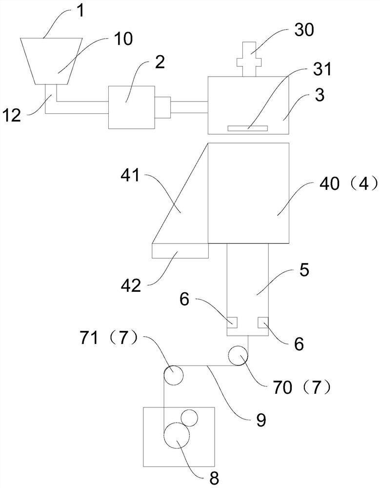
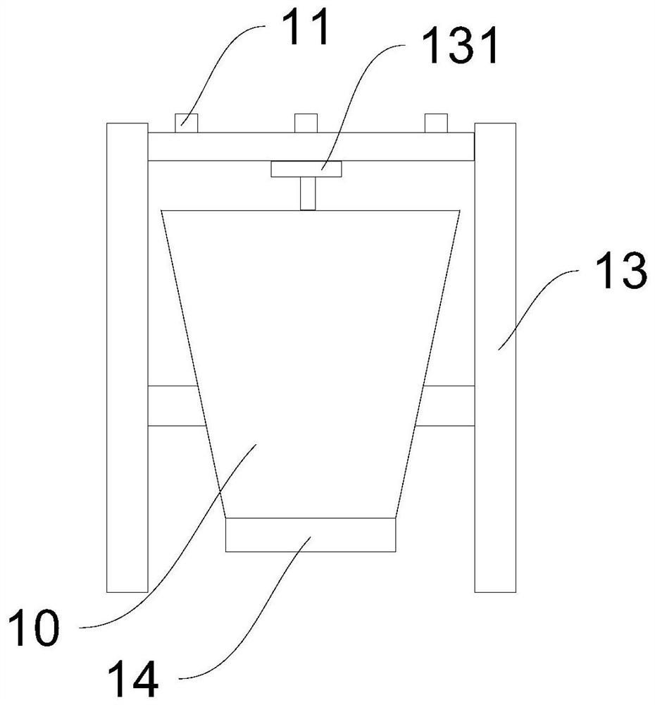
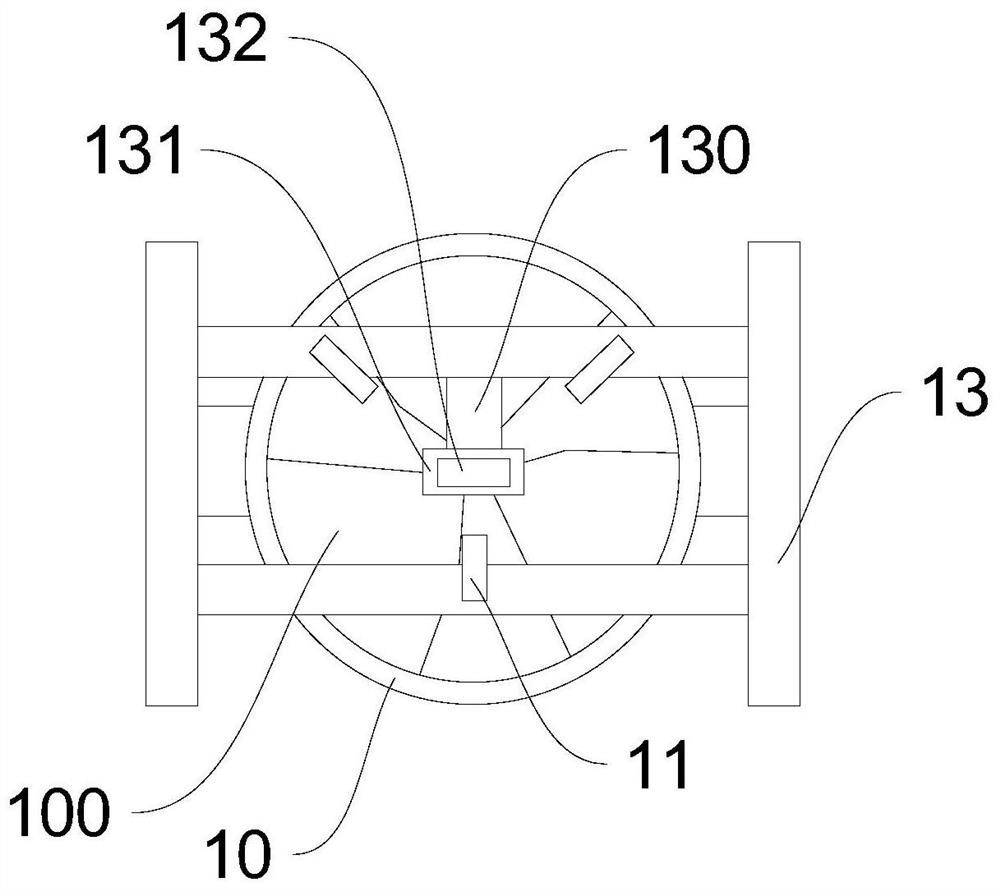
[0026] Embodiment one: if figure 1 As shown, an ultra-high-speed spinning device for producing HOY filaments provided in this embodiment includes a feeding device 1, a screw extruder 2, a spinning box 3, a side blowing device 4, and an oiling device arranged in sequence. Device 6, godet 7 and winder 8, feeding device 1 comprises funnel 10 and is used to add the feed pipe 11 of raw material in funnel 10, and funnel 10 below is provided with discharge pipe 12, and discharge pipe 12 and The feeding port of the screw extruder 2 is connected, and the bottom of the funnel 10 is also rotated with a turntable 14. The spinning raw materials are initially stirred by the turntable 14, and then added to the screw extruder 2. The outlet of the screw extruder 2 Connected with the melt inlet of the spinning box 3, the screw extruder 2 makes the raw material into a molten substance by extruding and melting, and then extrudes the molten substance into the spinning box 3 through the melt inlet....

Embodiment 2

[0030] Embodiment two: if Figure 5 and Figure 6 As shown, a kind of ultra-high-speed spinning device for producing HOY yarn provided by this embodiment, the difference between this embodiment and the above-mentioned embodiment is that the air outlet of the air duct 41 in this embodiment communicates with the bellows 40, and the air duct The air inlet of 41 is connected with a fan 42, and the air duct 41 is provided with an air duct partition plate 410, which is used to divide the air duct 41 into multiple air supply paths.

[0031] Based on the above-mentioned distinguishing technical features, by setting the air duct partition plate 410, the air duct 41 is divided into a plurality of air supply paths, and each air supply path supplies air to different height ranges in the bellows 40, so that it can Adjust the cooling air volume and wind speed accordingly at the height.

[0032] The air duct partition plate 410 in this embodiment includes a first partition plate 411 and a ...


PUM


Abstract

The invention discloses an ultra-high-speed spinning device for producing HOY. The ultra-high-speed spinning device comprises a feeding device, a screw extruder, a spinning manifold, a side blowing device, an oiling device, a draw-off godet and a winding head which are arranged in sequence; the feeding device comprises a funnel, a feeding pipe and a discharging pipe; the discharging pipe is connected with the screw extruder; the side blowing device comprises an air bellow; the air bellow is arranged below the spinning manifold; a sliver channel is connected to the lower portion of the air bellow; the oiling device is arranged in the sliver channel; the draw-off godet is arranged below the sliver channel; the winding head is arranged below the draw-off godet; the winding head comprises a machine base, a spinning cake roller and a friction roller; a lifting motor connected with the friction roller is arranged on the machine base; a control module and an electric sensor are arranged on the lifting motor; a pressure sensor is arranged on the friction roller; and the pressure sensor and the electric sensor are both connected with the control module. The whole structure of the spinning device can be reduced, the complexity is reduced, and meanwhile the spinning efficiency is improved.

Description

technical field [0001] The invention belongs to the field of spinning devices, in particular to an ultra-high-speed spinning device for producing HOY filaments Background technique [0002] Highly oriented yarn (HOY) refers to the one-step ultra-high-speed spinning method, which has a high degree of fiber molecular orientation and good dyeing performance of the fiber. The so-called ultra-high-speed spinning refers to the melt spinning method whose spinning speed is higher than the usual spinning speed. The general winding speed can reach 5000m / min, and the strength and elongation of the obtained fibers can reach commercial general standards. Without any additional drawing, the use of ultra-high-speed spinning can greatly increase the output, and can also reduce the production cost due to the reduction of drawing steps. However, due to the high spinning speed, the requirements for the spinning device are higher. For example, the winding head winds the filament to the cake ro...

Claims


Application Information

Patent Timeline
Patent Type & Authority Applications(China)
IPC IPC(8): D01D5/092D01D1/04
CPCD01D5/092D01D1/04
Inventor 赵洪辉高广亮
Owner 诸暨市新丝维纤维有限公司
Learn More